
Constant current source circuit

A technology of constant current source and current regulation circuit, which is applied in the direction of circuits, electrical components, laser components, etc., can solve the problems of laser power reduction, shortened service life, and semiconductor laser performance deterioration, and achieve the effect of avoiding the impact

Pending Publication Date: 2017-10-24
HFB PHOTONICS CO LTD
View PDF6 Cites 1 Cited by
  • Summary
  • Abstract
  • Description
  • Claims
  • Application Information

AI Technical Summary

Problems solved by technology

[0002] The drive of the semiconductor laser requires a constant current source. The conventional constant current source will generate different degrees of overshoot current in the modulation mo

Method used


Image

  • Constant current source circuit
  • Constant current source circuit

Examples


Embodiment Construction

[0022] Below in conjunction with accompanying drawing and specific embodiment the present invention is described in further detail:

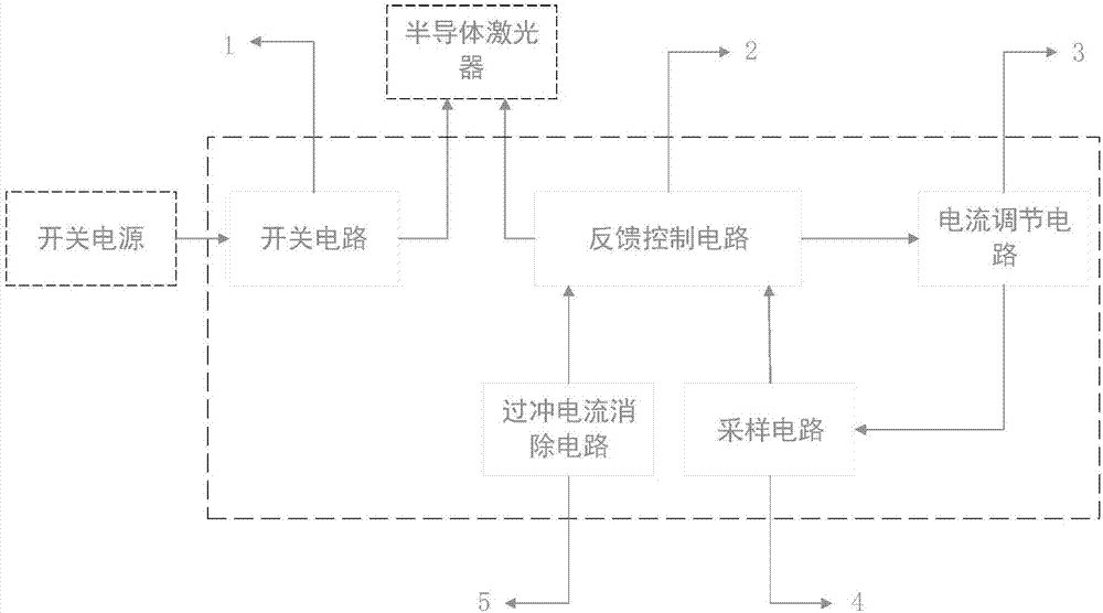
[0023] A constant current source circuit, its structure is as follows figure 1 As shown, it includes a switch circuit 1, a feedback control circuit 2, a current regulation circuit 3, a sampling circuit 4 and an overshoot current elimination circuit 5;

[0024] A switch circuit 1 configured to turn on or turn off power supply for the laser semiconductor laser;

[0025] The feedback control circuit 2 is configured to differentially amplify the sampling voltage and the reference voltage to generate a voltage for controlling the current regulation circuit 3;

[0026] A current regulation circuit 3 configured to generate a required current signal;

[0027] The sampling circuit 4 is configured to convert the current signal into a voltage signal;

[0028] The overshoot current elimination circuit 5 is configured to eliminate the overshoot of the mod...


PUM


Abstract

The invention discloses a constant current source circuit, belonging to the technical field of fiber lasers. The constant current source circuit includes a switch circuit, a feedback control circuit, a current adjusting circuit, a sampling circuit, and an overshoot current elimination circuit. The overshoot current elimination circuit can eliminate the overshoot current in the modulation mode and realize a constant current source without overshoot current, thereby avoiding the influence of the overshoot current on a semiconductor laser.

Description

technical field [0001] The invention belongs to the technical field of fiber lasers, and in particular relates to a constant current source circuit. Background technique [0002] The drive of the semiconductor laser requires a constant current source. The conventional constant current source will generate different degrees of overshoot current in the modulation mode. The overshoot current will cause the performance of the semiconductor laser to deteriorate, the laser power will drop significantly, and the service life will be shortened. permanent damage. Contents of the invention [0003] Aiming at the above-mentioned technical problems existing in the prior art, the present invention proposes a constant current source circuit, which has a reasonable design, overcomes the deficiencies of the prior art, and has good effects. [0004] In order to achieve the above object, the present invention adopts the following technical solutions: [0005] A constant current source cir...

Claims


Application Information

Patent Timeline
IPC IPC(8): H01S5/042
CPCH01S5/042
Inventor 徐琛潇李锦辉赵一柱陈祥雪缪秋滚韩宗涛
Owner HFB PHOTONICS CO LTD
Features
  • Generate Ideas
  • Intellectual Property
  • Life Sciences
  • Materials
  • Tech Scout
  • Unparalleled Data Quality
  • Higher Quality Content
  • 60% Fewer Hallucinations
Learn More