Lamp for vehicle and vehicle with the same
A technology for lamps and vehicles, which is applied in the direction of headlights, vehicle parts, lighting device parts, etc., can solve the problem that it is difficult to form a light distribution pattern in the irradiation range, and achieve the effect of uniform clarity
- Summary
- Abstract
- Description
- Claims
- Application Information
AI Technical Summary
Problems solved by technology
Method used
Image

Examples
no. 1 approach
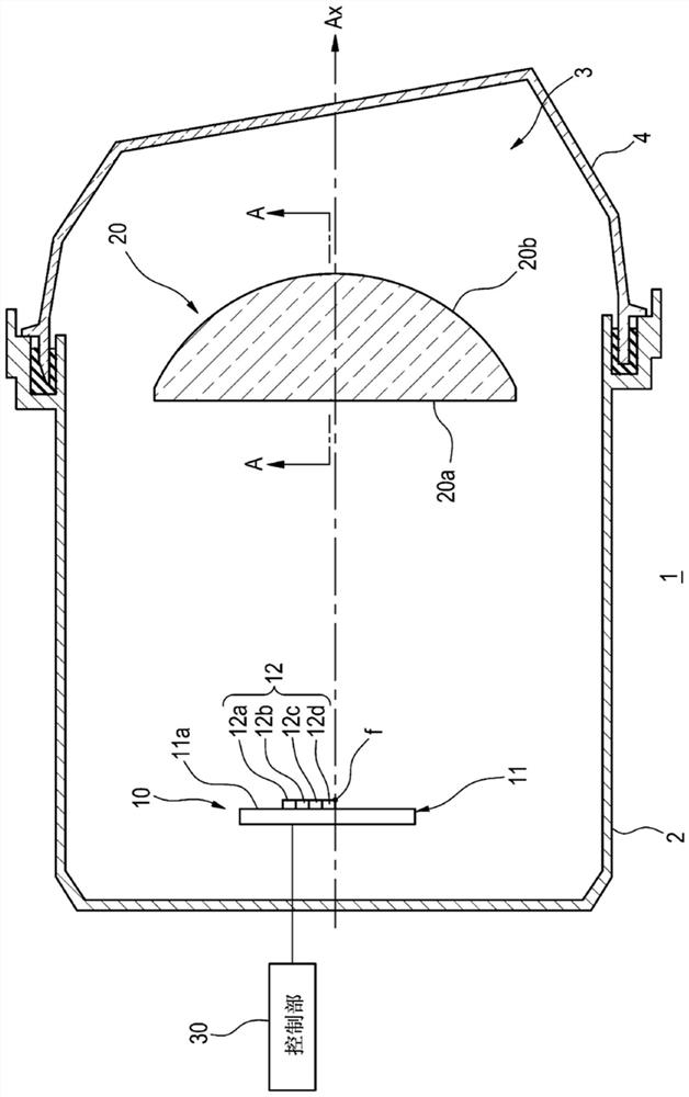
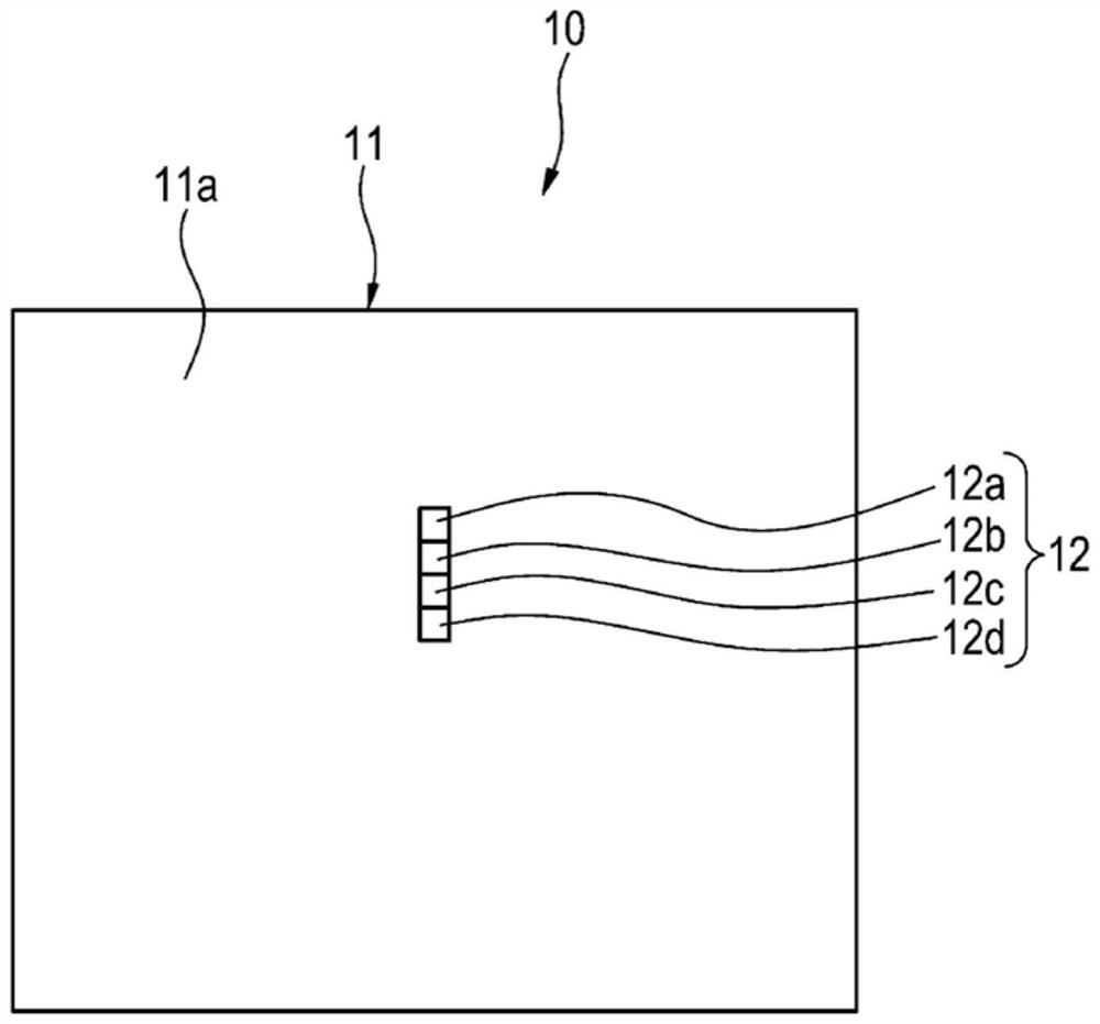
[0042] figure 1 is a vertical sectional view showing a schematic structure of the vehicle lamp according to the first embodiment of the present invention, figure 2 It is a front view showing the light source unit of the lamp according to the first embodiment.
[0043] The vehicle lamp 1 (hereinafter referred to as the lamp 1 ) according to the present embodiment is a lamp unit for road surface painting (road surface painting device) mounted on at least one of a pair of headlamps arranged on the left and right sides in front of the vehicle. exist figure 1 In the diagram, the structure of a road surface drawing lamp unit mounted on one of the headlamps is shown as the lamp 1 .
[0044] Such as figure 1 As shown, the lamp 1 includes: a lamp body 2 having an opening on the vehicle front side; and a translucent cover 4 attached so as to cover the opening of the lamp body 2 . The translucent cover 4 is formed of translucent resin, glass, or the like. A light source unit 10 and...
no. 2 approach
[0060] Image 6 It is a vertical cross-sectional view showing the road surface drawing lamp according to the second embodiment.
[0061] A lamp 100 according to the second embodiment includes a light source unit 110 and a projection lens 120 . The configuration of the projection lens 120 is the same as that of the projection lens 20 of the first embodiment, and thus detailed description thereof will be omitted.
[0062] The light source unit 110 has: a substrate 111 ; and at least one LED chip 112 mounted on the substrate 111 . The substrate 111 is arranged such that its chip mounting surface 111 a faces the incident surface 120 a of the projection lens 120 . The light source unit 110 is supported by an unillustrated rotating mechanism, such as Image 6 As shown, the light-emitting surface of the LED chip 112 can be directed obliquely downward from the state facing the front of the lamp (become Image 6 The orientation of the light source unit 110 shown by the dotted line ...
no. 3 approach
[0066] Figure 7 It is a perspective view showing a schematic structure of a vehicle lamp according to a third embodiment. In addition, in Figure 8 (a) and (b) show the moving state of the movable shade which concerns on 3rd Embodiment.
[0067] The lamp 200 according to the present embodiment is a lamp unit for road surface drawing (road surface drawing device) mounted on at least one of a pair of headlamps arranged on the left and right sides in front of the vehicle. exist Figure 7 In the figure, the structure of the road surface drawing lamp unit mounted on one of the headlamps is shown as the lamp 200 , and the illustration of the lamp body and the translucent cover is omitted.
[0068] Such as Figure 7 As shown, the lamp 200 has a light source unit 210, a projection lens 220, and a movable shade 230 (an example of a shade member). Each structural element is attached to a lamp body by the support mechanism which is not shown in figure. The configuration of the pro...
PUM
 Abstract
Description
Claims
Application Information