
Optical module and electronic equipment

A technology of optical module and photosensitive surface, which is applied in the field of optical imaging, and can solve problems such as affecting the quality of image imaging and difficulty in changing and adjusting the structure of the optical module

Pending Publication Date: 2021-05-28
BEIJING JIIOV TECH CO LTD
View PDF7 Cites 0 Cited by
  • Summary
  • Abstract
  • Description
  • Claims
  • Application Information

AI Technical Summary

Problems solved by technology

[0004] An optical module usually includes multiple optical components that need to be set and fixed in relation to each other according to specific focal length and other parameters. After the optical components of the optical module are assembled and fixed inside the electronic device, the structure of the optical module will It is difficult to change and adjust, which will affect the imaging quality of the image

Method used


Image

  • Optical module and electronic equipment
  • Optical module and electronic equipment
  • Optical module and electronic equipment

Examples


Embodiment Construction

[0033] The technical solutions in the embodiments of the present application will be clearly and completely described below in conjunction with the drawings in the embodiments of the present application.

[0034] In the description of this application, it should be noted that the orientation or positional relationship indicated by the terms "inner", "outer", etc. is based on the orientation or positional relationship shown in the drawings, or the usual placement of the application product when it is used. Orientation or positional relationship is only for the convenience of describing the present application and simplifying the description, and does not indicate or imply that the referred device or element must have a specific orientation, be constructed and operated in a specific orientation, and thus should not be construed as limiting the present application. In addition, the terms "first", "second", etc. are only used for distinguishing descriptions, and should not be const...


PUM

PropertyMeasurementUnit
viewing angleaaaaaaaaaa

Abstract

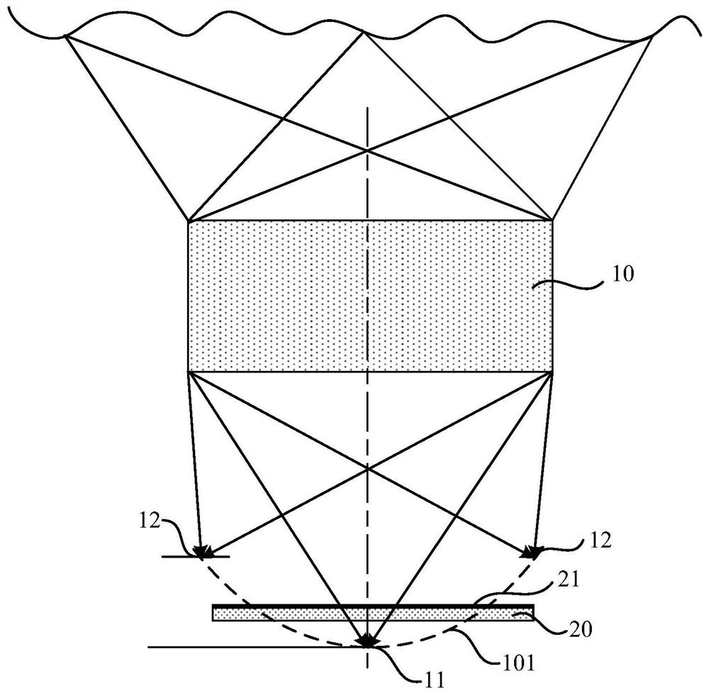
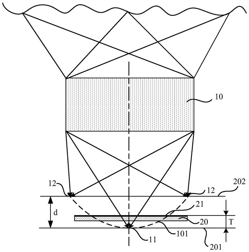
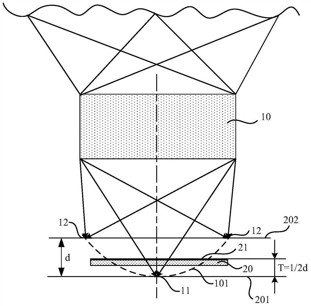
The invention provides an optical module and electronic equipment, relates to the technical field of optical imaging, and can improve the imaging quality when the optical module is applied to the electronic equipment through the arrangement of each optical element in the optical module. The optical module comprises a lens component and an image sensor arranged on the imaging side of the lens component, the imaging surface of the lens component on a to-be-recognized object is an arc-shaped image surface, the light-sensitive surface of the image sensor is arranged between the lowest point of the arc-shaped image surface and the highest point of the arc-shaped image surface, the optical module is used for fingerprint recognition, and the to-be-recognized object is a fingerprint. The optical module can balance the distance from the light-sensitive surface to the central area of the imaging surface and the distance from the light-sensitive surface to the edge area of the imaging surface, and balance the definition of the image received by the light-sensitive surface of the image sensor, so that the definition of the image with biological information received by the image sensor is relatively balanced; therefore, the biological information can be extracted and analyzed from the clear image for recognition, and the recognition accuracy of the optical module on the to-be-recognized object is improved.

Description

technical field [0001] The present application relates to the technical field of optical imaging, in particular to an optical module and electronic equipment. Background technique [0002] With the development of portable terminal equipment represented by mobile phones, the application of biometric technology is becoming more and more extensive and in-depth. Taking electronic devices as an example, fingerprint recognition, fingerprint verification, face recognition, etc., have been more and more used in the screen wake-up of display devices and the identity authentication steps of various programs, improving the security and usage of display devices flexibility. [0003] In the prior art, an optical module is installed in an electronic device, such as a fingerprint module for fingerprint identification, or a lens module for taking pictures of faces or capturing video images, etc. The location of the recognition is different, the recognition or collection area can be set in...

Claims


Application Information

Patent Timeline
Patent Type & Authority Applications(China)
IPC IPC(8): G06K9/00G02B13/00G02B7/02
CPCG02B13/00G02B7/02G06V40/1347G06V40/1318
Inventor 张林
Owner BEIJING JIIOV TECH CO LTD
Learn More