Radiation image conversion panel and manufacturing method thereof

a technology of image conversion panel and conversion screen, which is applied in the direction of conversion screen, instruments, nuclear engineering, etc., can solve the problems of significant damage to diagnostic capability, and achieve the effect of uniform sharpness distribution and significant improvement of image characteristics

Inactive Publication Date: 2005-06-09
KONICA MINOLTA MEDICAL & GRAPHICS INC
View PDF13 Cites 0 Cited by
  • Summary
  • Abstract
  • Description
  • Claims
  • Application Information

AI Technical Summary

Benefits of technology

[0016] According to 3, since a stimulable fluorescent substance layer is formed by arranging an evaporation source so that all the acute angles θ1, formed by the plane direction of a support and the normal directions, which connect arbitrary points in.a unit evaporation region on a support and the center of an evaporation source, satisfy 50°≦θ1≦90°, a slope distribution of columnar crystals which constitute a stimulable fluorescent substance layer becomes uniform in a radiation image conversion panel, which results in a uniform sharpness distribution in the plane. Therefore, image characteristics can be significantly improved.

Problems solved by technology

However, in a stimulable fluorescent substance layer provided with columnar crystals described in above JP-A No. 2-58000, sharpness as an image capability depends on a slope of columnar crystals and determines a sharpness distribution in a radiation image conversion panel plane, while a slope distribution of the columnar crystal in the plane was not defined resulting in non-uniform sharpness in the plane to cause a problem of significantly damaging of diagnostic capability.

Method used


Image

  • Radiation image conversion panel and manufacturing method thereof
  • Radiation image conversion panel and manufacturing method thereof

Examples


example 1

(Preparation of Radiation Image Conversion Panel)

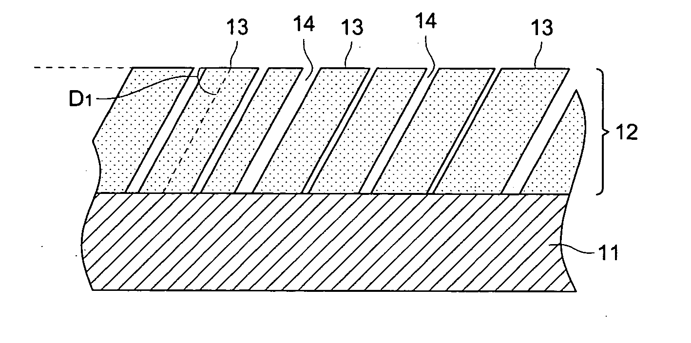
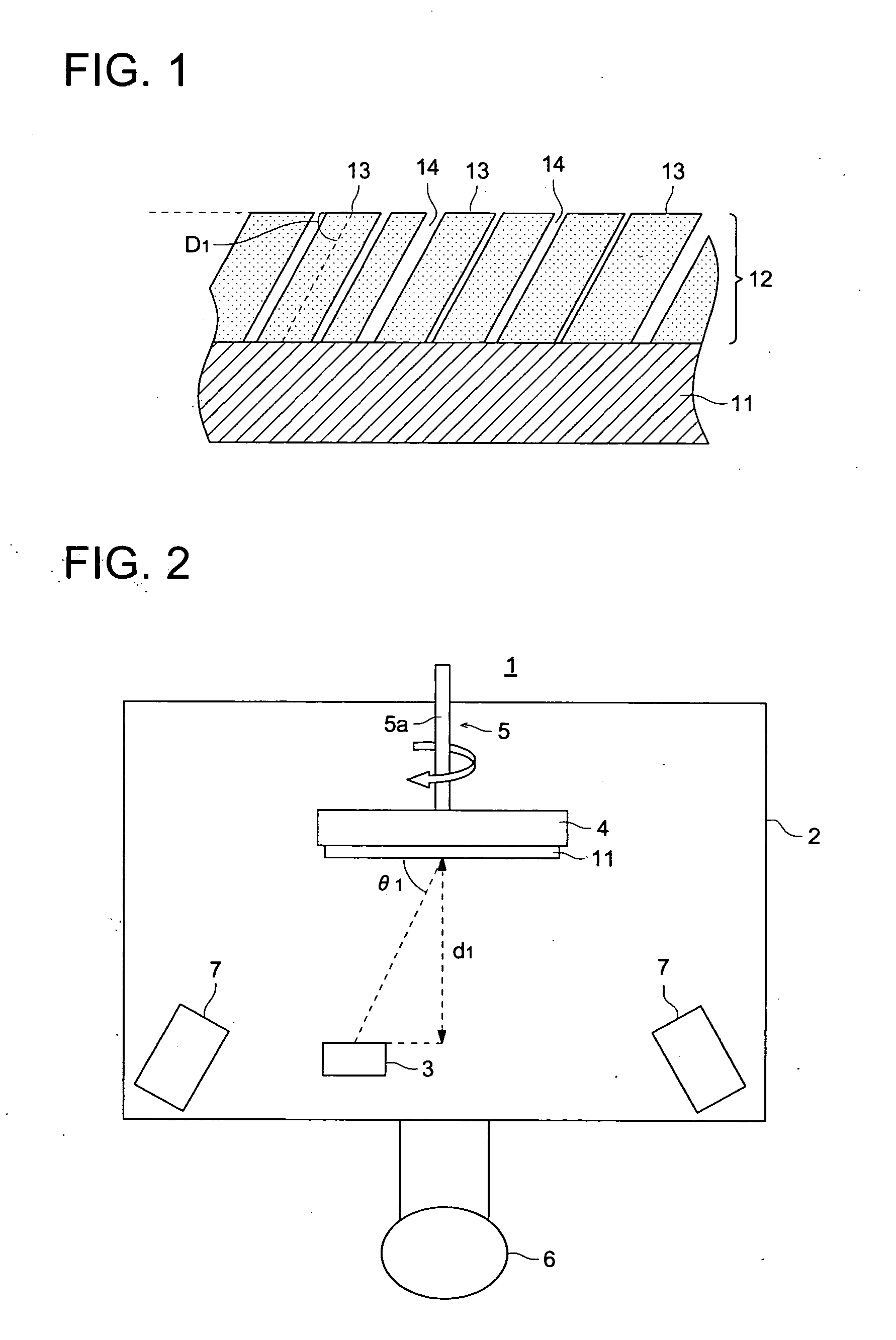
[0072] A stimulable fluorescent substance layer having a columnar structure comprising a stimulable fluorescent substance (CsBr:Eu) was formed on the one side of a support utilizing evaporation equipment 1 shown in FIG. 2.

[0073] As a support, a CFPR support having a size of 500 mm×500 mm was utilized.

[0074] First, the above fluorescent substance raw material as an evaporation material was filled in a resistance heating crucible while support 11 was mounted on rotating support holder 4, and evaporation source 3 was arranged so as to make acute angle θ1, which is formed by the plane direction of support 11 and a normal line connecting the center of support 11 and the center of evaporation source 3, of 50° as well as distance d1 between support 11 and evaporation source 3 was adjusted to 420 mm.

[0075] Subsequently, after the inside of evaporation equipment 1 was once evacuated and a vacuum degree was adjusted to 1.0×10⁻² Pa by intro...

example 2

[0077] A radiation image conversion panel was prepared in a similar manner to example 1, except that distance d1 between a support and an evaporation source was adjusted to 610 mm and acute angle θ1 to 60°.

example 3

[0078] A radiation image conversion panel was prepared in a similar manner to example 1, except that distance d1 between a support and an evaporation source was adjusted to 970 mm and acute angle θ1 to 70°.


PUM

PropertyMeasurementUnit
thicknessaaaaaaaaaa
temperatureaaaaaaaaaa
angleaaaaaaaaaa

Abstract

A radiation image conversion panel which is provided with a stimulable fluorescent substance layer containing a stimulable fluorescent substance layer containing a stimulable fluorescent substance formed by a gas phase accumulating method on a support, wherein said stimulable fluorescent substance layer is constituted on a columnar crystal structure, and slopes D1 and D23 satisfy 0°≦|D1−D2|≦40°, when acute angles formed by said radiation image conversion panel surface and normal lines passing through the center of said columnar crystals, with respect to columnar crystals at arbitrary two points in the radiation image conversion panel plane, are designated as slopes of columnar crystals, D1 and D2.

Description

FIELD OF THE INVENTION [0001] The present invention relates to a radiation image conversion panel provided with a stimulable fluorescent substance layer, which contains a stimulable fluorescent substance formed by a gas phase method, on a support, and a manufacturing method of a radiation image conversion panel. BACKGROUND OF THE INVENTION [0002] Heretofore, a so-called radiation method which applies a silver salt to obtain a radiation image has been utilized, while a method to convert a radiation image into a visual image without using a silver salt has been developed. That is, developed has been a method in which radiation, which passed through a photographic object, is absorbed by a stimulable fluorescent substance, thereafter this stimulable fluorescent substance is excited with a certain type of energy to make radiation energy accumulated in this stimulable fluorescent substance be emitted as fluorescent light, which is detected to be made into an visual image. [0003] As a spec...

Claims


Application Information

Patent Timeline
Patent Type & Authority Applications(United States)
IPC IPC(8): C09K11/00C09K11/61C09K11/77C23C14/06C23C14/22C23C14/24C23C14/26C23C14/54G01T1/00G03B42/02G21K4/00
CPCC09K11/7733C23C14/06G21K4/00C23C14/26C23C14/541C23C14/226
Inventor MISHINA, NORIYUKIYANAGITA, TAKAFUMIMAEZAWA, AKIHIRO
Owner KONICA MINOLTA MEDICAL & GRAPHICS INC
Why Eureka
Try Eureka