
Charge detection circuit and terminal equipment

A charging detection and terminal equipment technology, applied in battery circuit devices, circuit devices, different battery charging directions, etc., can solve problems such as safety accidents, inability to realize human-computer interaction, and inability of electronic devices to generate prompt information.

Active Publication Date: 2017-10-27
诸暨市澳速机械设计工作室
View PDF7 Cites 0 Cited by
  • Summary
  • Abstract
  • Description
  • Claims
  • Application Information

AI Technical Summary

Problems solved by technology

However, the inventor found that there are at least the following problems in the prior art: in the prior art solution to this problem, a reminder message can only be generated when the temperature at the charging connector rises rapidly during the charging process when the electronic device is turned on To remind the user, and when the electronic device is charging in the off state, if the temperature at the charging connector rises rapidly, the electronic device cannot generate a prompt message to remind the user (shutdown cannot realize human-computer interaction), thus causing the electronic device to Charging in the off state may cause safety accidents

Method used


Image

  • Charge detection circuit and terminal equipment
  • Charge detection circuit and terminal equipment

Examples


Embodiment Construction

[0014] In order to make the purpose, technical solutions and advantages of the embodiments of the present invention more clear, various implementation modes of the present invention will be described in detail below in conjunction with the accompanying drawings. However, those of ordinary skill in the art can understand that, in each implementation manner of the present invention, many technical details are provided for readers to better understand the present application. However, even without these technical details and various changes and modifications based on the following implementation modes, the technical solution claimed in this application can also be realized.

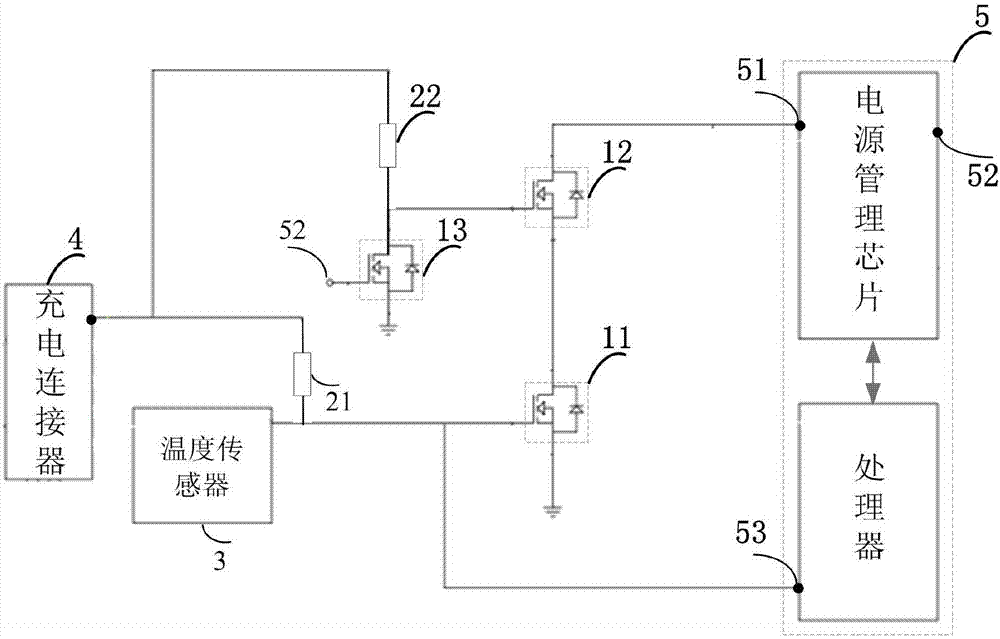
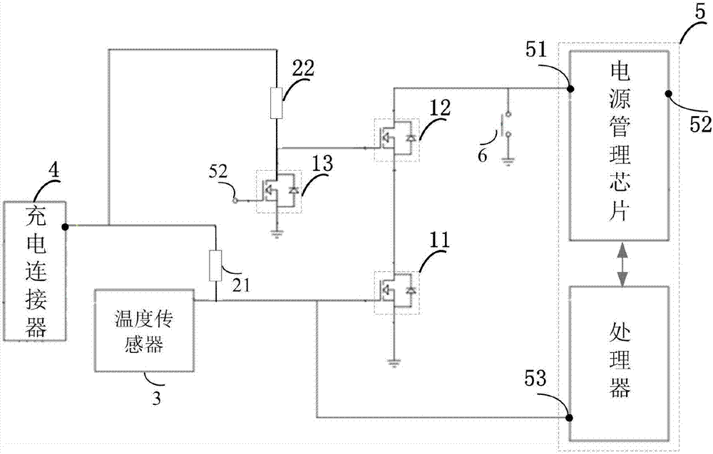
[0015] The first embodiment of the present invention relates to a charging detection circuit, which is applied to a terminal including a control module and a charging connector, such as a mobile phone; figure 1 As shown, the charging detection circuit includes: a first NMOS transistor 11 , a second NMOS tran...


PUM


Abstract

Embodiments of the invention relate to the technical field of electronic products and disclose a charge detection circuit and terminal equipment. The charge detection circuit in the embodiments of the invention comprises a first NMOS tube, a second NMOS tube, a third NMOS tube and a temperature sensor, wherein a grid electrode of the first NMOS tube is connected to the temperature sensor and a drain electrode of the first NMOS tube is connected to a source electrode of the second NMOS tube; the grid electrode of the second NMOS tube is connected to the drain electrode of the third NMOS tube and a charging connector, and the drain electrode of the second NMOS tube is connected to a control module; and the temperature sensor is controlled to a third pin of the control module and the charging connector. According to the embodiments of the invention, when the terminal is turned off to charge, if the charging connector works abnormally to cause temperature rise, the terminal can boot automatically and generate a prompt message, so that a condition that an accident happens in a shutdown charging process is avoided, and the safety of equipment is improved.

Description

technical field [0001] The embodiments of the present invention relate to the technical field of electronic products, and in particular to a charging detection circuit and a terminal device. Background technique [0002] With the rapid development of electronic devices such as mobile phones and tablet computers, the problem of battery life has become increasingly prominent. People improve battery life by introducing high-current charging into electronic devices, that is, the imported current gradually transitions from 0.5 amps to 1 amps. An, and then to the commonly used 2A (or even higher). However, for the weak current system in the electronic equipment, the imported current of 2 amps and above 2 amps is already very large. Impedance requirements are higher. If the impedance on the charging line works abnormally, the charging connector will work abnormally and the temperature at the connector will rise rapidly, which will affect the charging quality and even cause the mob...

Claims


Application Information

Patent Timeline
IPC IPC(8): H02J7/00
CPCH02J7/0036H02J7/0047
Inventor 孙皓刘廷
Owner 诸暨市澳速机械设计工作室
Learn More