Digital window and display device
A digital and preset quantity technology, applied in optics, instruments, nonlinear optics, etc., can solve the problems of single PDLC drive mode and inability to apply digital display fields, and achieve the effect of improving display efficiency
- Summary
- Abstract
- Description
- Claims
- Application Information
AI Technical Summary
Problems solved by technology
Method used
Image
Examples
Embodiment 1
[0041] An embodiment of the present invention provides a digital window, the digital window includes at least three electrode layers and at least two PDLC film layers, and is used to display preset content.
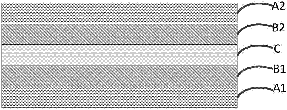
[0042] Optionally, the digital window is set as a rectangle, such as figure 1 As shown, it includes: the first electrode layer A1, the first PDLC thin film layer B1, the second electrode layer C, the second PDLC thin film layer B2 and the third electrode layer A2 are sequentially arranged from bottom to top; wherein,
[0043] The first electrode layer A1 includes a first preset number of electrode sheets arranged in M rows in the longitudinal direction; M is a positive integer; the first preset number is the number of each column;
[0044] The third electrode layer A2 includes a second preset number of electrode sheets in N columns arranged in the short side direction; N is a positive integer; the second preset number is the number of each row;
[0045] The sides of t...
Embodiment 2
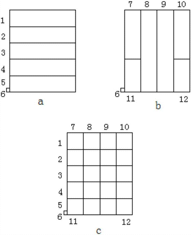
[0052] The embodiment of the present invention provides a digital window, such as figure 2 As shown, the digital window is a 4*5 matrix display unit ( figure 2 As shown in figure c), the digital window includes the first electrode layer A1 ( figure 2 shown in figure a) and the third electrode layer A2 ( figure 2 shown in Figure b). The first PDLC film layer, the second PDLC film layer and the second electrode layer C ( figure 2 (not shown in ) refer to Embodiment 1, and will not be introduced here.
[0053] It should be noted that the digital window in the embodiment of the present invention is designed according to a commonly used rectangle, so the five layers of materials constituting the digital window are also rectangular. Wherein, the long side direction refers to the straight line where the long side of the rectangle is located, and the short side direction refers to the straight line where the wide side of the rectangle is located.
[0054] In the embodiment o...
Embodiment 3
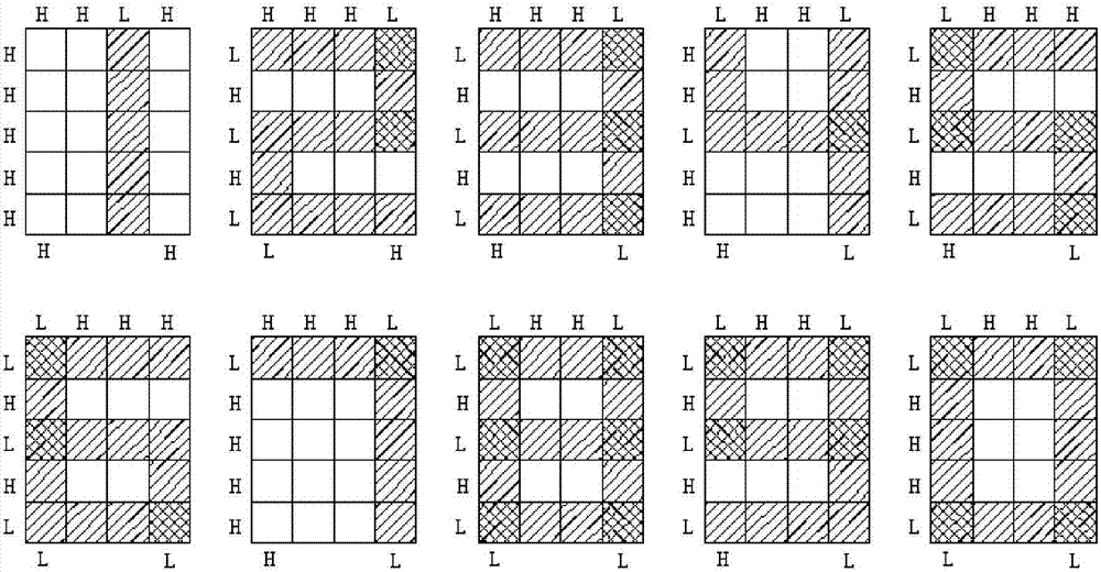
[0070] The embodiment of the present invention also provides a digital window, such as Figure 5 As shown, the digital window is a 4*5 matrix display unit ( Figure 5 As shown in Figure c), this digital window has the same structure as the digital window provided in the embodiment, the difference is that: the first electrode layer A1 is etched 4 times in the long side direction to form 5 electrode sheets, and then from Divide each obtained electrode sheet into two equal electrode sheets in the direction of the broad side, and finally get the following Figure 5 For the 10 electrode sheets shown in the figure a, the first column is coded as 21-25, and the second column is coded as 26-30. The third electrode layer A2 is etched three times in the widthwise direction to form four electrode sheets, which are sequentially coded as 31-34. The common electrode 35 is connected to the second electrode layer C. Finally, the first electrode layer A1 is overlapped with the third electro...
PUM
 Abstract
Description
Claims
Application Information
 - R&D
- Intellectual Property
- Life Sciences
- Materials
- Tech Scout
- Unparalleled Data Quality
- Higher Quality Content
- 60% Fewer Hallucinations
Browse by: Latest US Patents, China's latest patents, Technical Efficacy Thesaurus, Application Domain, Technology Topic, Popular Technical Reports.
© 2025 PatSnap. All rights reserved.Legal|Privacy policy|Modern Slavery Act Transparency Statement|Sitemap|About US| Contact US: help@patsnap.com


