
Jig-saw furniture

A furniture and connector technology, applied in the field of furniture, can solve problems such as inconvenient assembly and disassembly, difficult to disassemble and move, and does not meet individual needs, etc., to achieve the effect of convenient use and convenient assembly and disassembly

Inactive Publication Date: 2017-11-03
曹高煜
View PDF5 Cites 0 Cited by
  • Summary
  • Abstract
  • Description
  • Claims
  • Application Information

AI Technical Summary

Problems solved by technology

[0002] The tables or stools in the existing furniture are usually designed by designers and then collectively produced by the factory. The situation is too qualitative, and most of the furniture is connected by screws, which is not easy to disassemble and move, and does not meet the individual needs of some people. For example, the tea table and desk used at home cannot be converted, or one or two of these furniture When a component is damaged, the entire furniture is basically reimbursed, because it is difficult to find the relevant accessories needed for repair, which is easy to cause waste of resources. For example, the patent application publication number 201020231288.0 discloses a splicing furniture. The furniture system includes several A rectangular frame, each rectangular frame includes four interconnected frames and a space surrounded by the four frames, and at least one plane plate, which is connected with the rectangular frame to form furniture. But in the process of using the above patent, It is impossible to change the style of the furniture according to the needs, and it is impossible to adjust the height of the furniture. Screws make it inconvenient to assemble and disassemble

Method used


Image

  • Jig-saw furniture
  • Jig-saw furniture
  • Jig-saw furniture

Examples


Embodiment Construction

[0015] The following will clearly and completely describe the technical solutions in the embodiments of the present invention with reference to the accompanying drawings in the embodiments of the present invention. Obviously, the described embodiments are only some, not all, embodiments of the present invention. Based on the embodiments of the present invention, all other embodiments obtained by persons of ordinary skill in the art without making creative efforts belong to the protection scope of the present invention.

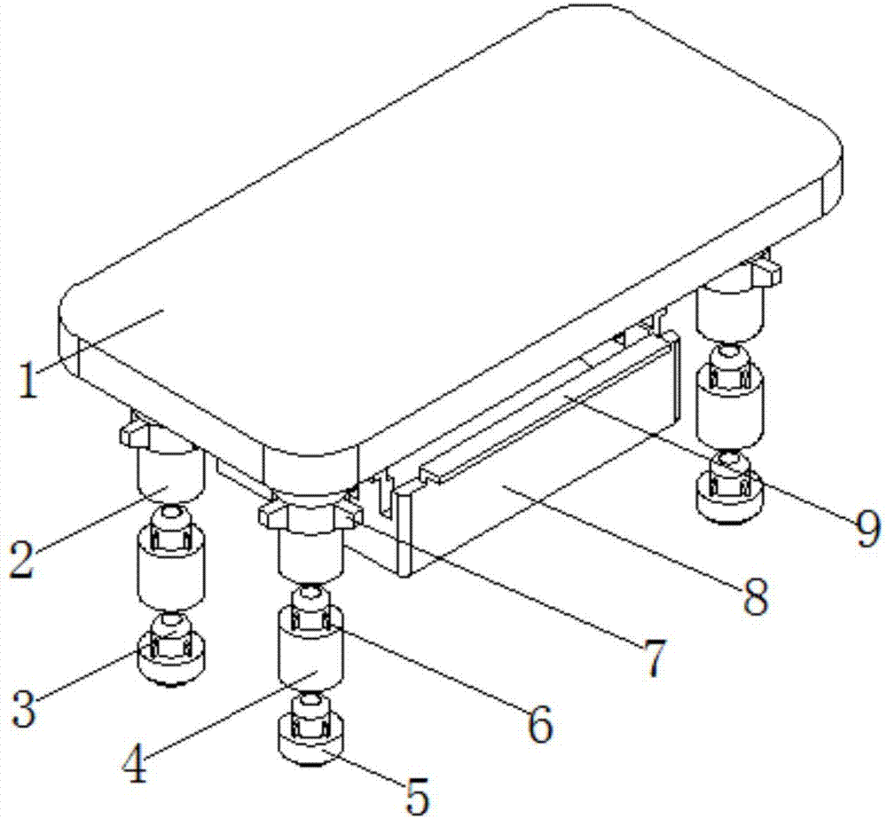
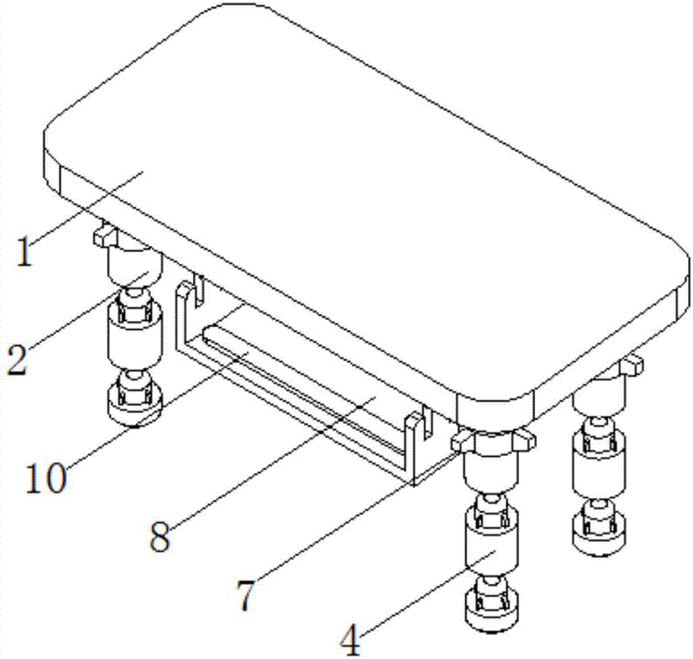
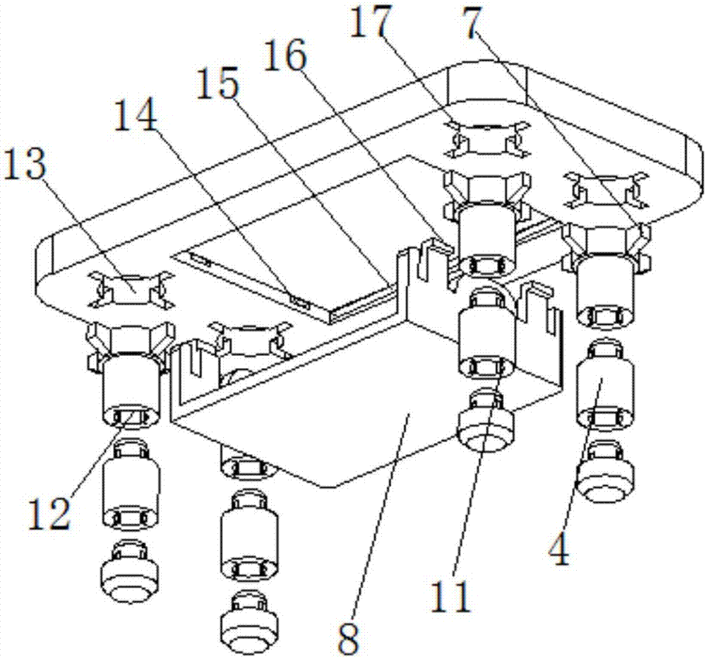
[0016] see Figure 1-3 , the present invention provides a technical solution: a splicing furniture, comprising a chopping board main body 1, one side of the chopping board main body 1 is provided with four groups of through grooves 13 equidistant and symmetrically distributed, and the chopping board main body 1 is connected with first One end of the column 2, the outside of the end of the first column 2 close to the chopping board main body 1 is provided with ...


PUM


Abstract

The invention discloses jig-saw furniture. The jig-saw furniture comprises a board main body, wherein four groups of through grooves which are symmetrically distributed equidistantly are formed in one side of the board main body; the board main body is connected with one end of a first stand column through the through grooves; a second stand column is arranged on one side, which is away from the board main body, of the first stand column; a connector is arranged on one side, which is close to the first stand column, of the second stand column; a connecting groove is formed in one side, which is close to the connector, of the first stand column; the connector is connected with the first stand column through the connecting groove; and a connecting groove is formed in one side, which is close to the connector, of the second stand column. By splicing of a shelf and the board main body, the style of the furniture can be changed as needed, and the use height of the furniture can be adjusted by changing of the number of the second stand columns between the first stand column and a third stand column; and by a splicing mode, the jig-saw furniture is convenient to assemble and disassemble; and stable connection can be realized by first angle fixing ribs and second angle fixing ribs, situations such as shaking can be avoided, and a user uses the jig-saw furniture conveniently.

Description

technical field [0001] The invention relates to the technical field of furniture, in particular to splicing furniture. Background technique [0002] The tables or stools in the existing furniture are usually designed by designers and then collectively produced by the factory. The situation is too qualitative, and most of the furniture is connected by screws, which is not easy to disassemble and move, and does not meet the individual needs of some people. For example, the tea table and desk used at home cannot be converted, or one or two of these furniture When a component is damaged, the entire furniture is basically reimbursed, because it is difficult to find the relevant accessories needed for repair, which is easy to cause waste of resources. For example, the patent application publication number 201020231288.0 discloses a splicing furniture. The furniture system includes several A rectangular frame, each rectangular frame includes four interconnected frames and a space ...

Claims


Application Information

Patent Timeline
Patent Type & Authority Applications(China)
IPC IPC(8): A47B3/06A47B13/00A47B41/00A47B9/00
Inventor 曹高煜
Owner 曹高煜
Learn More