
Electric table tripod and its coupling and electric table using the table tripod

A technology of couplings and table legs, applied in the field of electric tables, can solve the problems such as the inability to effectively reduce the assembly cost of technicians, the unfavorable stacking and placement of electric tables, and the unreasonable transportation costs, and improve the inventory and inventory. Effectiveness of management, increased overlapping area, and reduced installation steps

Active Publication Date: 2019-12-20
第一传动科技股ふん有限公司
View PDF6 Cites 0 Cited by
  • Summary
  • Abstract
  • Description
  • Claims
  • Application Information

AI Technical Summary

Problems solved by technology

[0003] Existing electric desks mainly include a table frame and at least two supporting legs connected to the table frame. Each supporting leg is provided with a lifting mechanism. The stacking and placement of electric tables is quite inconvenient during transportation, and the transportation cost is also expensive
[0004] In order to effectively solve the aforementioned problems of inconvenient transportation and high transportation costs, the industry adopts a separate design to overcome the problems of each support leg and table frame. Each support leg and table frame are driven by a motor and multiple transmission shafts. , the motor and the drive shaft are connected by a coupling, so that a single motor can be used to drive each support foot up and down
However, there are many problems such as the alignment and adjustment of the drive shaft during the assembly process. Therefore, after the customer purchases in batches, he must send a large number of assembly technicians to carry out the combination of the supporting legs and the table. As a result, the assembly cost of technicians cannot be effectively reduced, and urgently needs to be improved

Method used


Image

  • Electric table tripod and its coupling and electric table using the table tripod
  • Electric table tripod and its coupling and electric table using the table tripod
  • Electric table tripod and its coupling and electric table using the table tripod

Examples


Embodiment Construction

[0074] The detailed description and technical content of the present invention are described below with the accompanying drawings, but the attached drawings are only for reference and illustration, and are not used to limit the present invention.

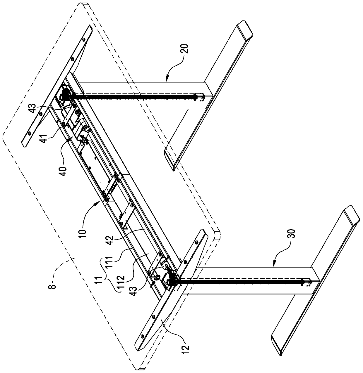
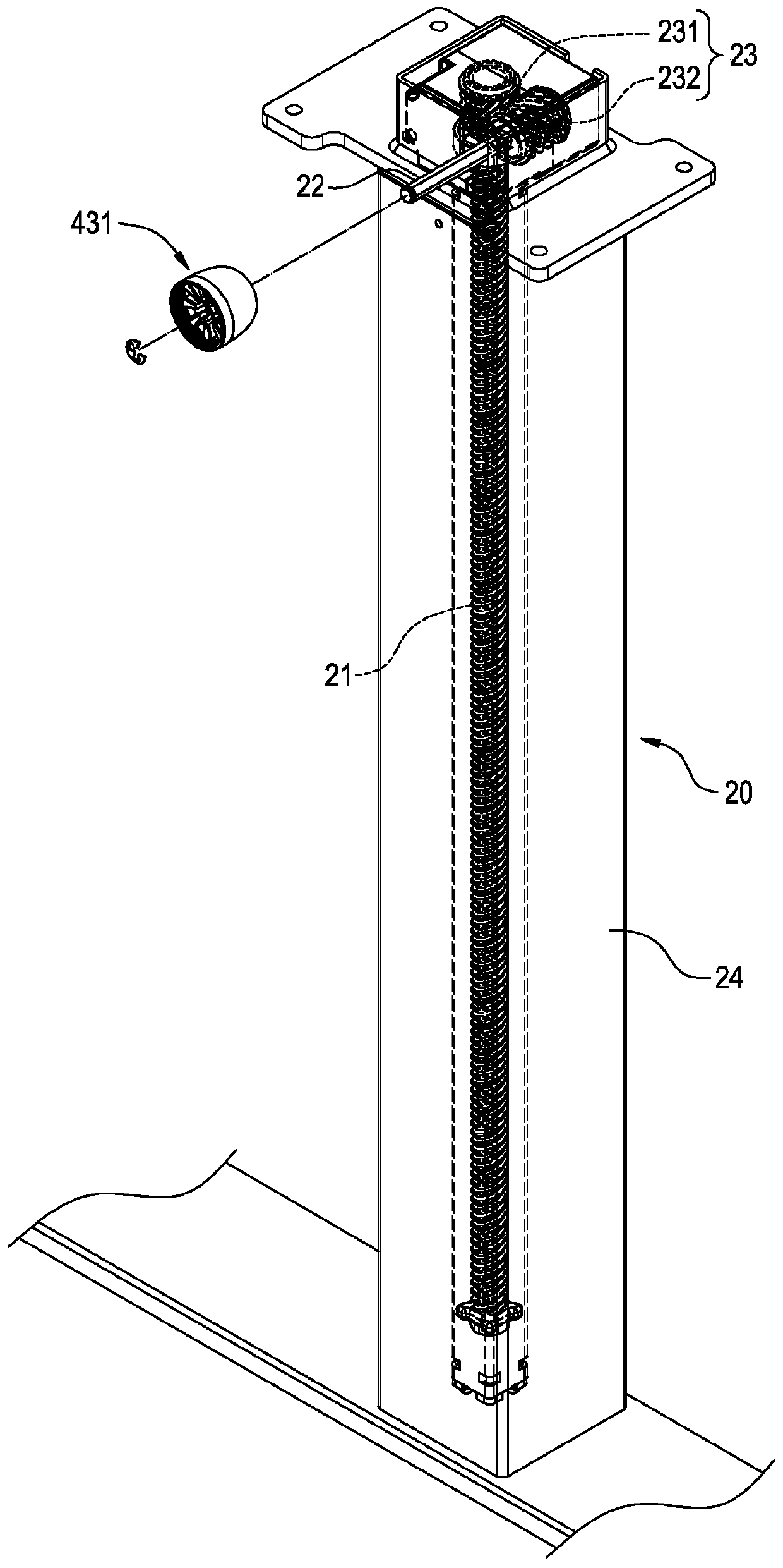
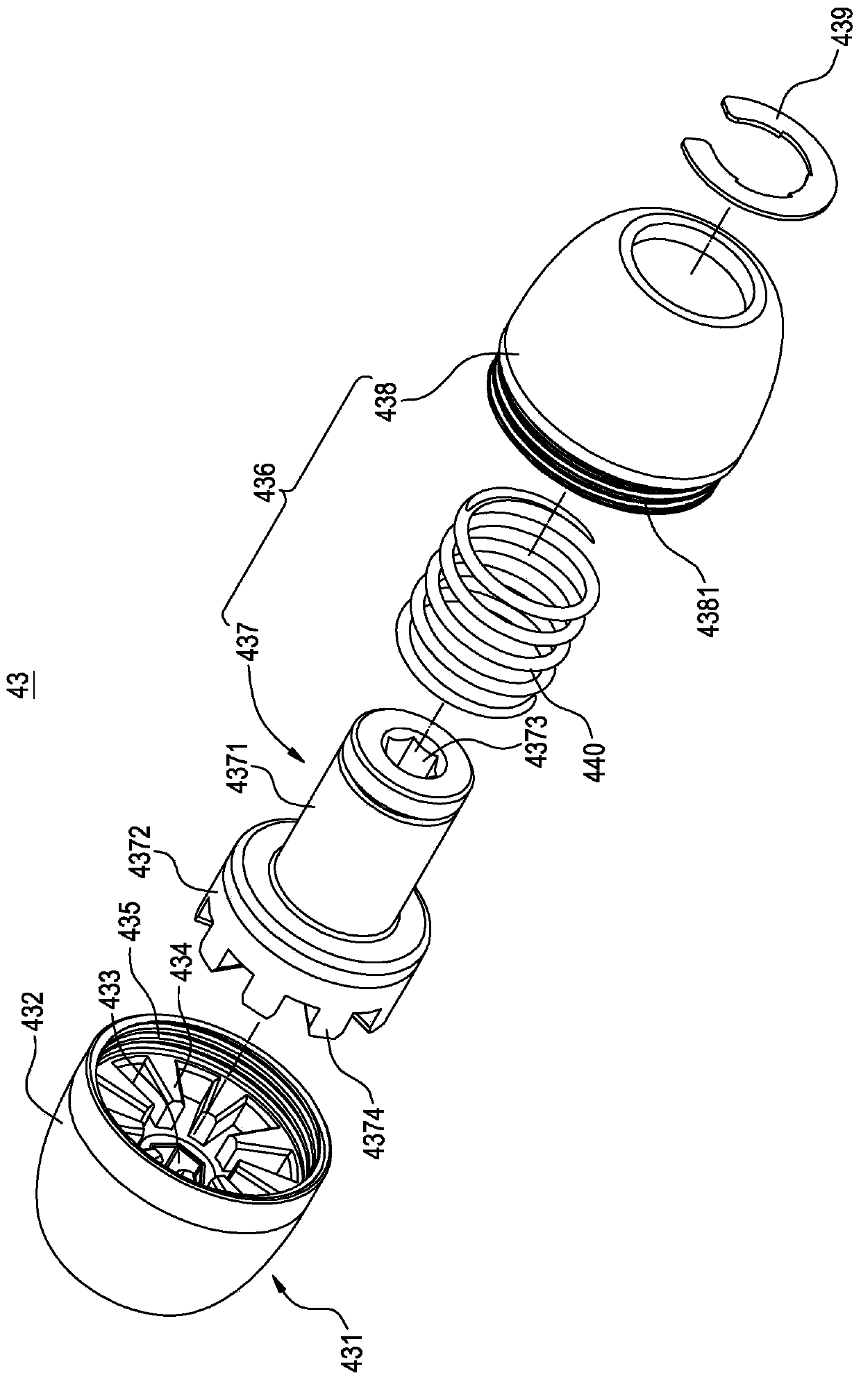
[0075] see Figure 1 to Figure 2 As shown, the present invention provides an electric table stand and its coupling and an electric table using the table stand, wherein the electric table stand mainly includes a carrier 10, at least two supporting legs 20, 30 and a transmission mechanism 40.

[0076] Carrier 10 is mainly used to provide a table board 8 to place, and its main

[0077]It includes a horizontal frame 11 and two side wings 12. The horizontal frame 11 is composed of two rectangular tubes 111 arranged side by side at intervals, and an accommodating groove 112 is formed between each rectangular tube 111. Each side wing 12 is connected to the horizontal frame 11 respectively. The first and last two ends, so that the carrier...


PUM


Abstract

The present invention relates to an electric table tripod and its coupling and an electric table using the table tripod, wherein the electric table tripod includes a carrier body, two supporting legs and a transmission mechanism, and each supporting leg is detachably connected to the The two ends of the carrier are parallel to each other, each supporting foot includes a screw and a first transmission shaft that drives the screw to rotate; the transmission mechanism is installed on the carrier, and the transmission mechanism includes a motor, a second transmission shaft driven by the motor and a coupling The coupling includes a first joint connected to the first transmission shaft, a second joint connected to the second transmission shaft, and an elastic body that elastically pushes the second joint to engage with the first joint. In this way, the fast combination of the supporting legs and the bearing body can be achieved, thereby saving the labor cost of assembly.

Description

technical field [0001] The invention relates to an electric table technology, in particular to an electric table stand and its coupling and an electric table using the table stand. Background technique [0002] Applying the lifting mechanism to the electric table can not only meet the body shape requirements of different users, but also allow users to adjust the height according to their personal preferences, so as to achieve the most comfortable use purpose. Therefore, the electric table with lifting function has become the current One of the mainstream of design. [0003] Existing electric desks mainly include a table frame and at least two supporting legs connected to the table frame. Each supporting leg is provided with a lifting mechanism. The stacking and placement of the electric table is quite inconvenient during transportation, and the transportation cost is also expensive. [0004] In order to effectively solve the aforementioned problems of inconvenient transpor...

Claims


Application Information

Patent Timeline
Patent Type & Authority Patents(China)
IPC IPC(8): A47B13/02A47B9/20
CPCA47B9/20A47B13/02A47B2200/0014A47B2200/0051A47B2013/022A47B2200/0056A47B9/04A47B2009/043A47B9/00A47B91/02A47B13/081A47B21/02A47B2200/004F16B12/10A47B13/00
Inventor 曾冠树
Owner 第一传动科技股ふん有限公司
Learn More