
Efficient energy-saving water-saving showering system and working method
A shower system, high-efficiency and energy-saving technology, applied in the field of bathroom shower systems, can solve the problems of short residence time, large water consumption, low heat utilization rate, etc., and achieve increased area and probability, high convective heat transfer coefficient, and large droplet surface area Effect
- Summary
- Abstract
- Description
- Claims
- Application Information
AI Technical Summary
Problems solved by technology
Method used
Image

Examples
Embodiment Construction
[0045] The present invention is proposed on the premise of solving the practicable processing technology. The present invention will be further described in detail below in conjunction with specific drawings.
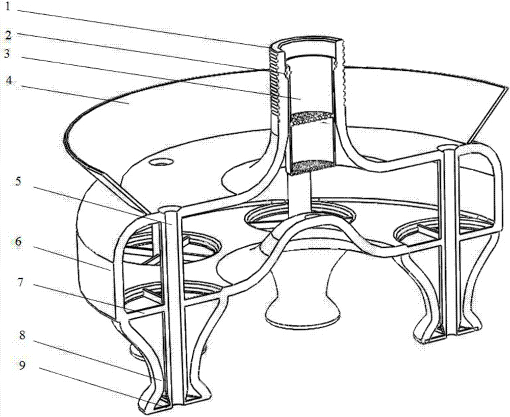
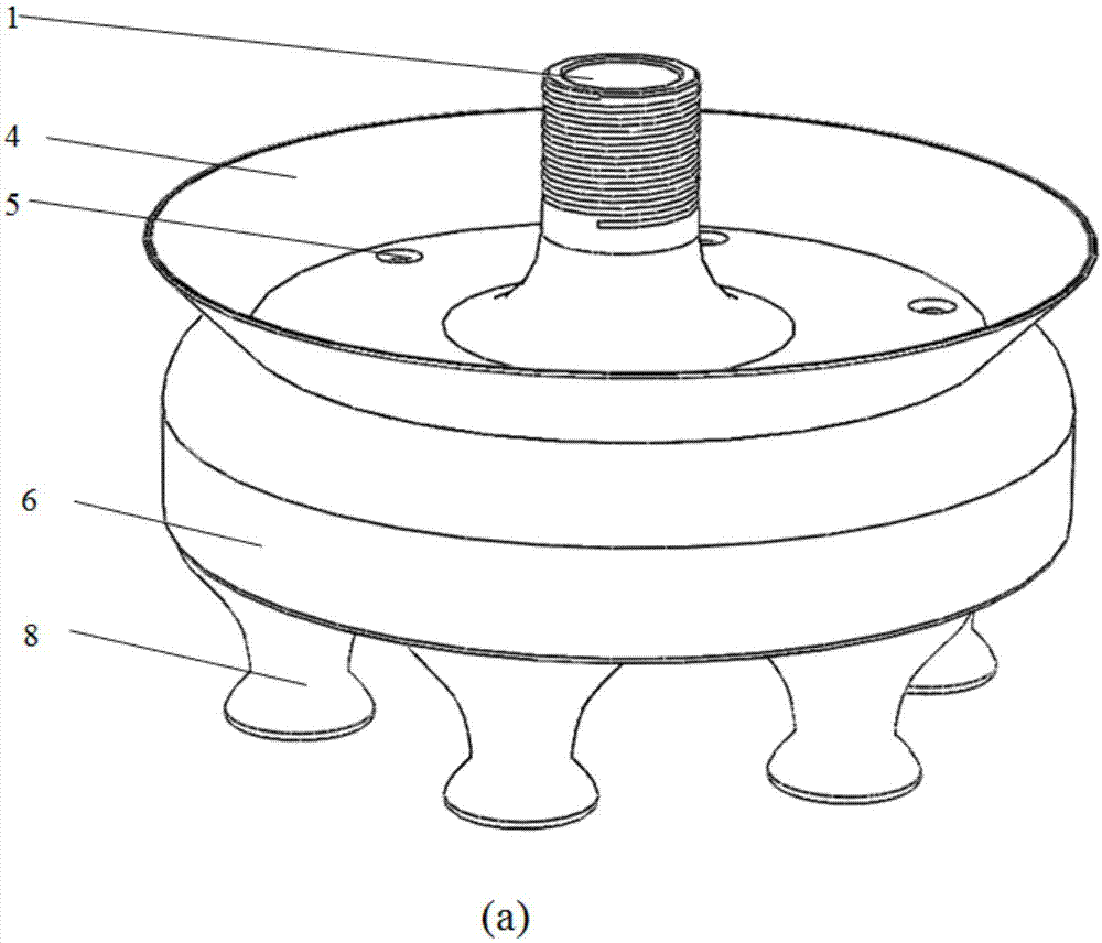
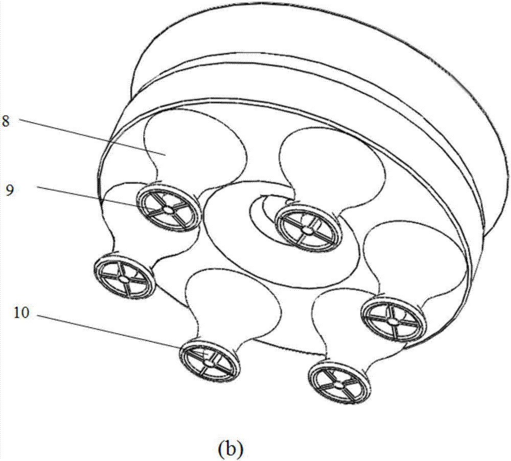
[0046] refer to figure 1 As shown, the present invention provides a high-efficiency, energy-saving and water-saving shower system, including a water inlet 1, a circular sealing ring 2, a multi-stage filter 3, a vapor-liquid recovery funnel 4, a vapor-liquid conduit 5, a main liquid chamber 6, and a nozzle inlet Reinforcing ribs 7, annular scaling nozzles 8, and nozzle outlet reinforcing ribs 9.
[0047] refer to Figure 1 to Figure 2 As shown, the water inlet 1 is located at the top of the main liquid chamber 6, and its outer wall is provided with external threads so as to be connected to the water supply pipe. A multistage filter 3 is installed in the water inlet 1 . After the mixture of cold water and hot water enters the system from the water inlet 1 at the top, ...
PUM
 Abstract
Description
Claims
Application Information