
Volatile solvent discharge method and equipment

A volatile solvent and equipment technology, applied in the field of solvent discharge, can solve the problems of high suction port position, insufficient to absorb volatile matter, and inability to effectively reduce harm, etc., and achieve the effect of preventing overflow.

Pending Publication Date: 2017-11-03
BASF SHANGHAI COATINGS CO LTD
View PDF11 Cites 2 Cited by
  • Summary
  • Abstract
  • Description
  • Claims
  • Application Information

AI Technical Summary

Problems solved by technology

Existing cleaning equipment is usually an open liquid tank without a cover or a cleaning box with a simple cover. There is no organized way to deal with air pollution and personnel health caused by the volatilization of cleaning solvents. It only relies on the suction arm and the worker's wear Labor protection measures such as masks cannot effectively reduce and control related hazards
[0003] Although common fume hoods can serve the purpose of removing solvents, they cannot be used in explosion-proof areas, and for high-concentration solvent volatiles, they can only be exhausted from the top. All volatiles, with no restrictions on volatiles spilled off the operating surface
[0004] In addition, the solvent replacement method in the cleaning tank is usually to manually carry the solvent barrel into it and lift it away from the waste solvent barrel after gravity discharge. Spill risk

Method used


Image

  • Volatile solvent discharge method and equipment
  • Volatile solvent discharge method and equipment

Examples


Embodiment Construction

[0032] The technical solution of the present invention will be described in detail below in conjunction with the accompanying drawings. The embodiments of the present invention are only used to illustrate the technical solutions of the present invention without limitation. Although the present invention has been described in detail with reference to the preferred embodiments, those skilled in the art should understand that the technical solutions of the invention can be modified or equivalently replaced , without departing from the spirit and scope of the technical solution of the present invention, all of which shall be covered by the claims of the present invention.

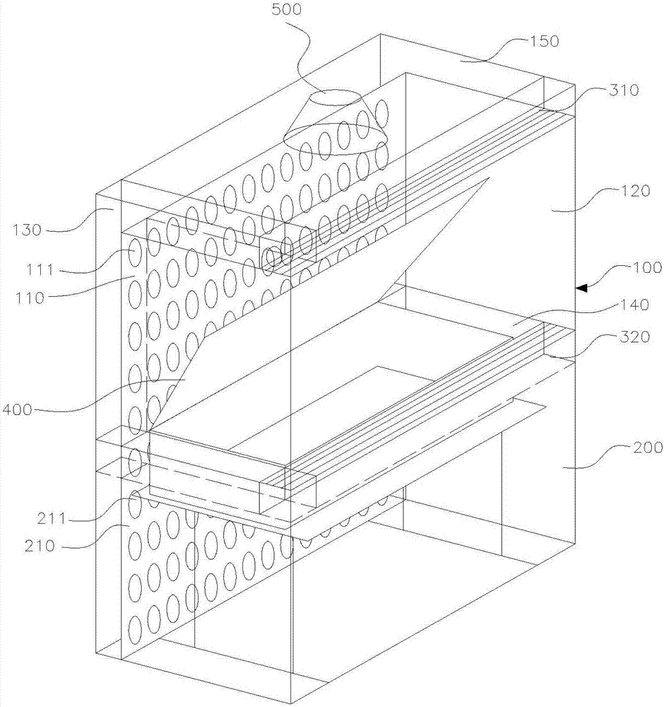
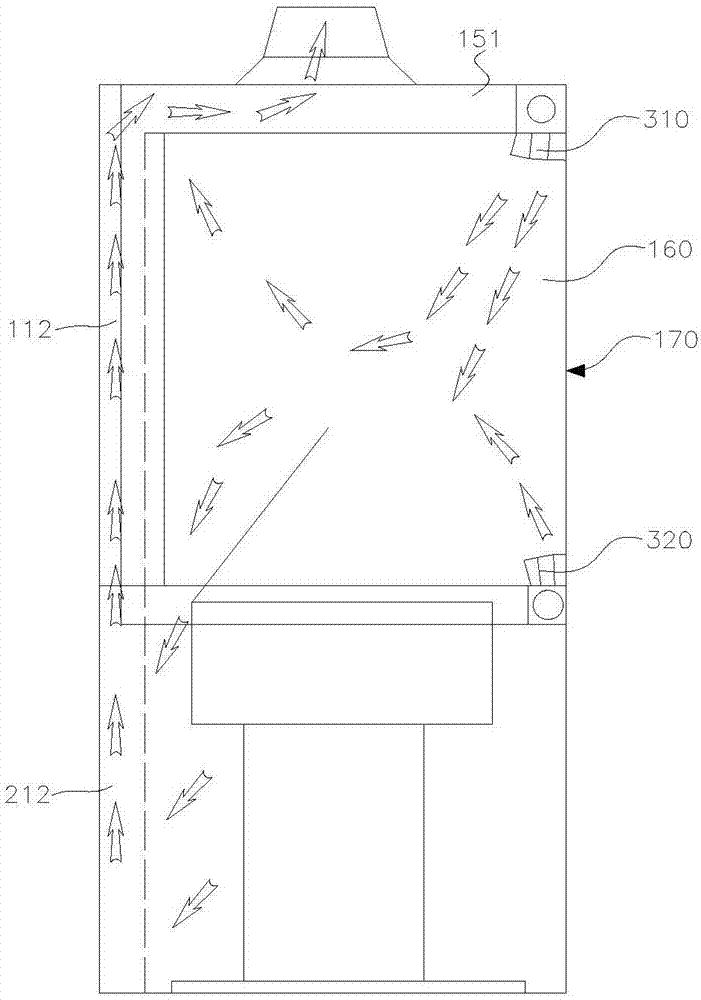
[0033] figure 1 It is a schematic structural diagram of an embodiment of the volatile solvent discharge device of the present invention, figure 2 It is a schematic diagram of an embodiment of the gas flow direction of the volatile solvent discharge device of the present invention. Such as figure 1 with fi...


PUM


Abstract

A volatile solvent discharge method comprises the steps that an air screen is formed in the window surface of a cleaning cabinet; then an air exhaust mechanism arranged at the top of the cleaning cabinet is started, so that an air flow of the air screen flows towards the cleaning cabinet; along with flowing of the air flow, the air flow and a volatile solvent in the cleaning cabinet also mutually act to form a solvent air flow; the solvent air flow is divided when meeting a flow guiding part which is arranged in the cleaning cabinet and forms an elevation angle with the plane of an operating table; part of the solvent air flow enters a first cavity channel through a first through hole of the upper end of a wall and is discharged by the air exhaust mechanism; and the other heavier part of the solvent air flow sinks under the effect of the flow guiding mechanism, enters a second cavity channel through a second through hole of the lower end of the wall and is discharged by the air exhaust mechanism. According to the method, the air screen is additionally arranged to conduct high-speed air relative blowing and sweeping, and the volatile solvent is blocked in the window surface; and meanwhile, air exhaust holes are formed in the vertical direction, and the cavity channels formed in the wall serve as air exhaust pipes, lead into an air pipe connector in the top of a cabinet body and then are in butt joint with a factory waste gas air exhaust system, so that the volatile solvent is timely extracted.

Description

technical field [0001] The invention relates to a solvent discharge method used in the cleaning process, in particular to an air curtain type discharge volatile solvent method and its equipment, which are used for cleaning small tools. Background technique [0002] The small tools that are often used in the production workshop need to be soaked in the cleaning solvent for manual cleaning, and the cleaning solvent needs to be replaced after cleaning. Existing cleaning equipment is usually an open liquid tank without a cover or a cleaning box with a simple cover. There is no organized way to deal with air pollution and personnel health caused by the volatilization of cleaning solvents. It only relies on the suction arm and the worker's wear Labor protection measures such as masks cannot effectively reduce and control related hazards. [0003] Although common fume hoods can serve the purpose of removing solvents, they cannot be used in explosion-proof areas, and for high-conce...

Claims


Application Information

Patent Timeline
IPC IPC(8): B08B15/02
CPCB08B15/023
Inventor 杨柏徐金龙
Owner BASF SHANGHAI COATINGS CO LTD
Learn More