
Stator iron core, single-phase permanent magnet motor and household appliances

A single-phase permanent magnet motor and stator core technology, applied in the fields of stator core, single-phase permanent magnet motor and household appliances, can solve the problems of increasing the length of the motor and increasing the length of the stator.

Active Publication Date: 2019-08-13
GUANGDONG WELLING ELECTRIC MACHINE MFG +1
View PDF5 Cites 0 Cited by
  • Summary
  • Abstract
  • Description
  • Claims
  • Application Information

AI Technical Summary

Problems solved by technology

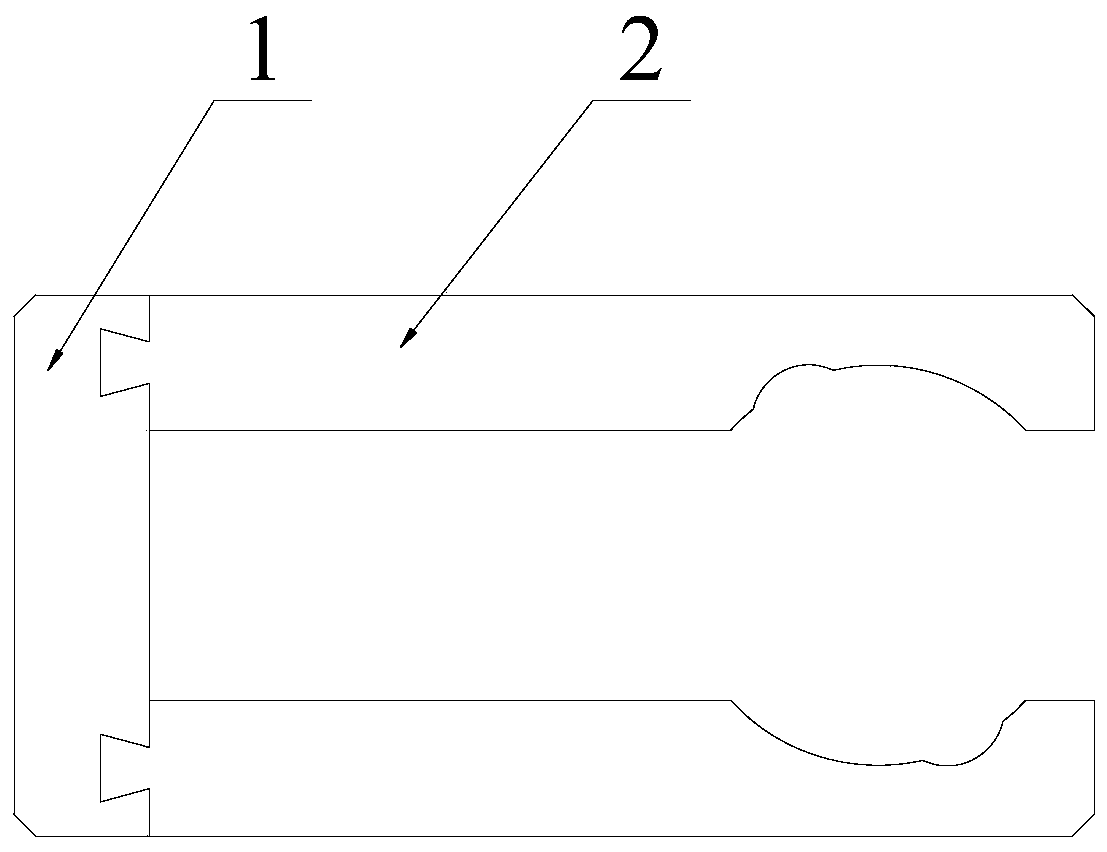
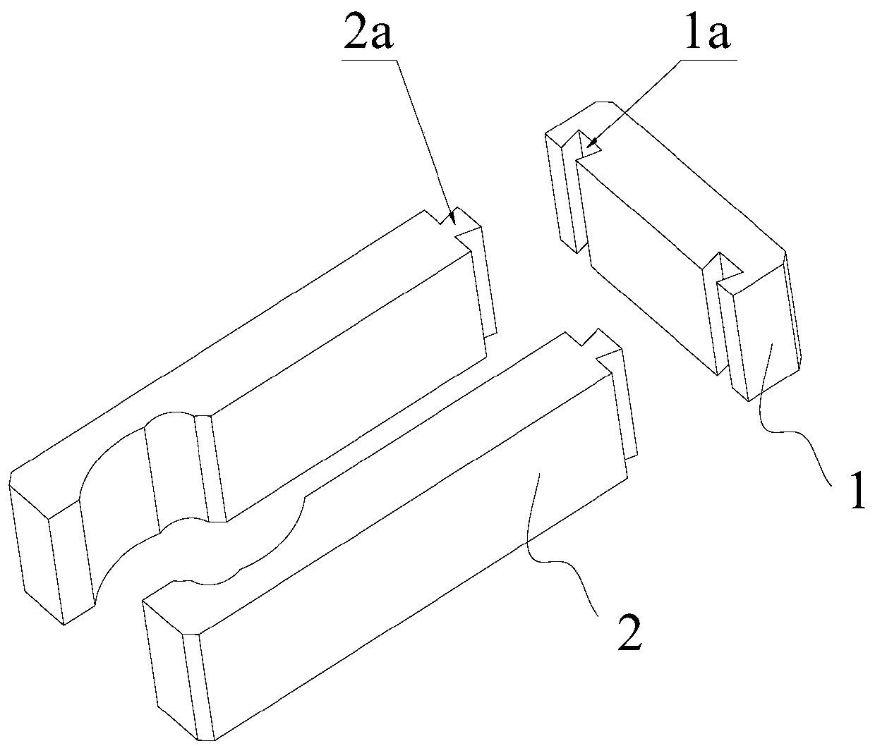
[0002] The traditional single-phase permanent magnet motor usually consists of stator core, winding and rotor, such as figure 1 and 2 As shown, the shape of the stator core is roughly U-shaped, which includes a yoke 1 and two separate arms 2, the yoke 1 is provided with a dovetail slot 1a, and the arm 2 is provided with a dovetail block 2a, In this solution, the yoke 1 and the arm 2 are connected through the cooperation of the dovetail groove 1a and the dovetail block 2a, and the connection and matching direction is parallel to the plane where the arm 2 is located, which will cause the length of the stator to increase, and further , so that the length of the motor increases

Method used


Image

  • Stator iron core, single-phase permanent magnet motor and household appliances
  • Stator iron core, single-phase permanent magnet motor and household appliances
  • Stator iron core, single-phase permanent magnet motor and household appliances

Examples


Embodiment Construction

[0033] Specific embodiments of the present invention will be described in detail below in conjunction with the accompanying drawings. It should be understood that the specific embodiments described here are only used to illustrate and explain the present invention, and are not intended to limit the present invention.

[0034] In the present invention, the terms "first", "second", ..., etc. are only used to distinguish different technical features, and are not used to limit the priority of technical features. When necessary, these technical features The effect that can be achieved is basically the same.

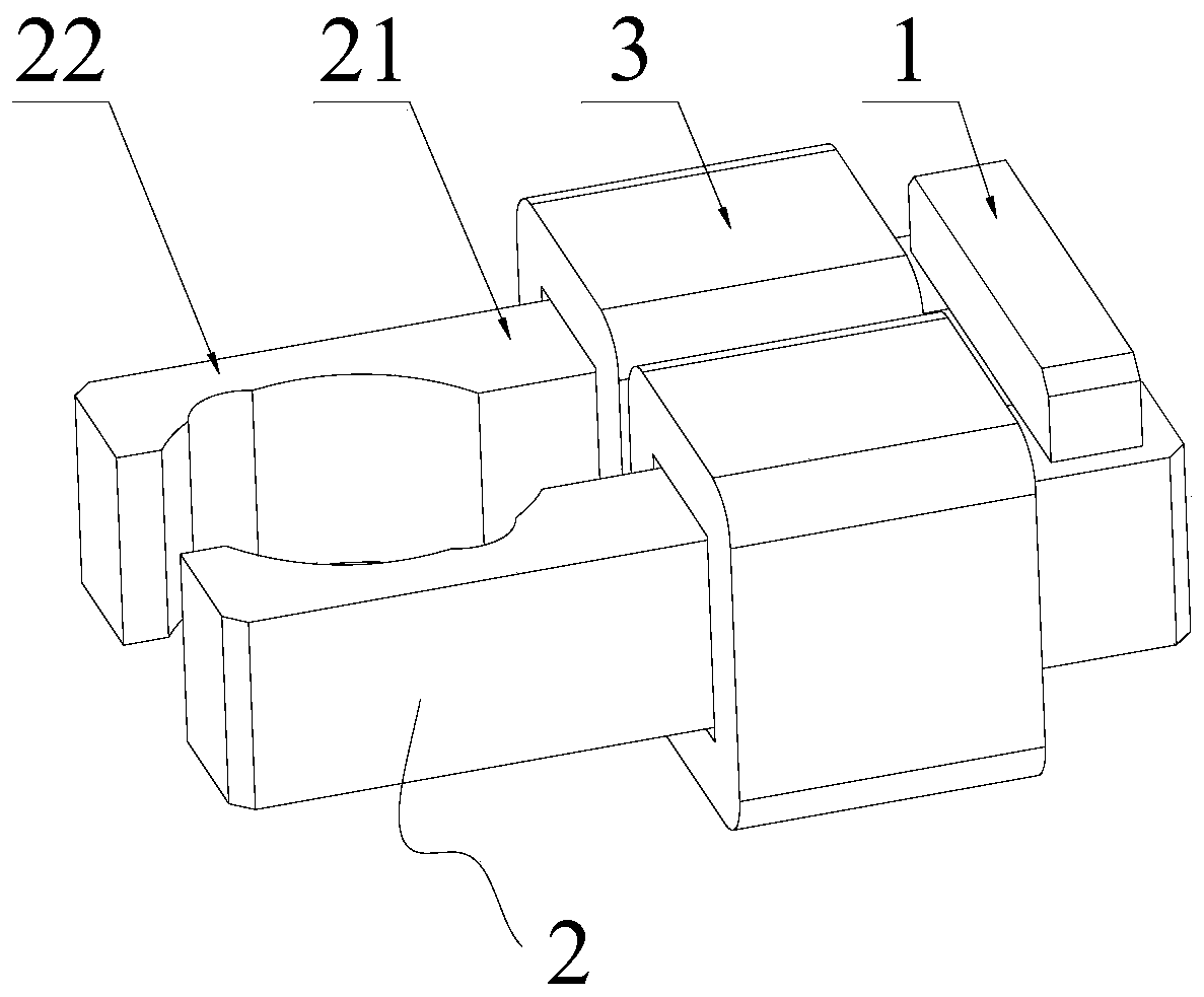
[0035] refer to Figure 3 to Figure 11 As shown, the present invention firstly provides a stator core, including a yoke 1 and two opposite arm parts 2, the arm parts 2 include a connecting arm 21 and a pole claw 22 arranged at the end of the connecting arm 21, two The pole claws 22 on the arm parts 2 face each other to form a space for accommodating the rotor, and the two ar...


PUM


Abstract

The invention relates to the technical field of motors, and discloses a stator core, a single-phase permanent magnet motor and household appliances. The stator core includes a yoke and two opposite arms. The arms include connecting arms and a set of On the pole claws at the ends of the connecting arms, the pole claws on the two arm parts are opposite to each other to form a space for accommodating the rotor, and the two arm parts are connected by the corresponding connecting arms. to the yoke portion and connected such that the yoke portion is located within the extended length of the connecting arm. The invention utilizes the space at the end of the coil winding to realize the connection between the yoke and the connecting arm under the condition that the yoke is located within the extended length range of the connecting arm. This arrangement does not increase the length of the motor and makes the motor The structure is more compact.

Description

technical field [0001] The invention relates to the technical field of motors, in particular to a stator core, a single-phase permanent magnet motor and household appliances. Background technique [0002] The traditional single-phase permanent magnet motor usually consists of stator core, winding and rotor, such as figure 1 and 2 As shown, the shape of the stator core is roughly U-shaped, which includes a yoke 1 and two separate arms 2, the yoke 1 is provided with a dovetail slot 1a, and the arm 2 is provided with a dovetail block 2a, In this solution, the yoke 1 and the arm 2 are connected through the cooperation of the dovetail groove 1a and the dovetail block 2a, and the connection and matching direction is parallel to the plane where the arm 2 is located, which will cause the length of the stator to increase, and further , so that the length of the motor increases. Contents of the invention [0003] The purpose of the present invention is to overcome the problem in ...

Claims


Application Information

Patent Timeline
Patent Type & Authority Patents(China)
IPC IPC(8): H02K1/14H02K21/16
CPCH02K1/141H02K1/145H02K21/16H02K2213/03
Inventor 朱嘉东王飞
Owner GUANGDONG WELLING ELECTRIC MACHINE MFG
Learn More