Motor powertrain and its bearing housing

A powertrain and bearing seat technology, applied in the direction of electric components, machines/engines, casings/covers/supports, etc., can solve problems such as bearing wear and affecting the service life of bearings, achieve consistent moving distances, and avoid deflection The effect of the force and the center position being unchanged

Active Publication Date: 2019-08-16
上海拓泓机械科技有限公司
View PDF5 Cites 0 Cited by
  • Summary
  • Abstract
  • Description
  • Claims
  • Application Information

AI Technical Summary

Problems solved by technology

The existing problem of this kind of bearing seat is: the two screw rods in each pair are independent of each other during adjustment, which may cause one screw rod to be twisted half a turn more or the other screw rod to be turned half a turn less, which will cause It will cause the final position of the bearing to not be in the center position, and the motor shaft will produce a deflection force on the bearing, which will cause the bearing to wear faster and affect the service life of the bearing

Method used


Image

  • Motor powertrain and its bearing housing
  • Motor powertrain and its bearing housing
  • Motor powertrain and its bearing housing

Examples


Embodiment Construction

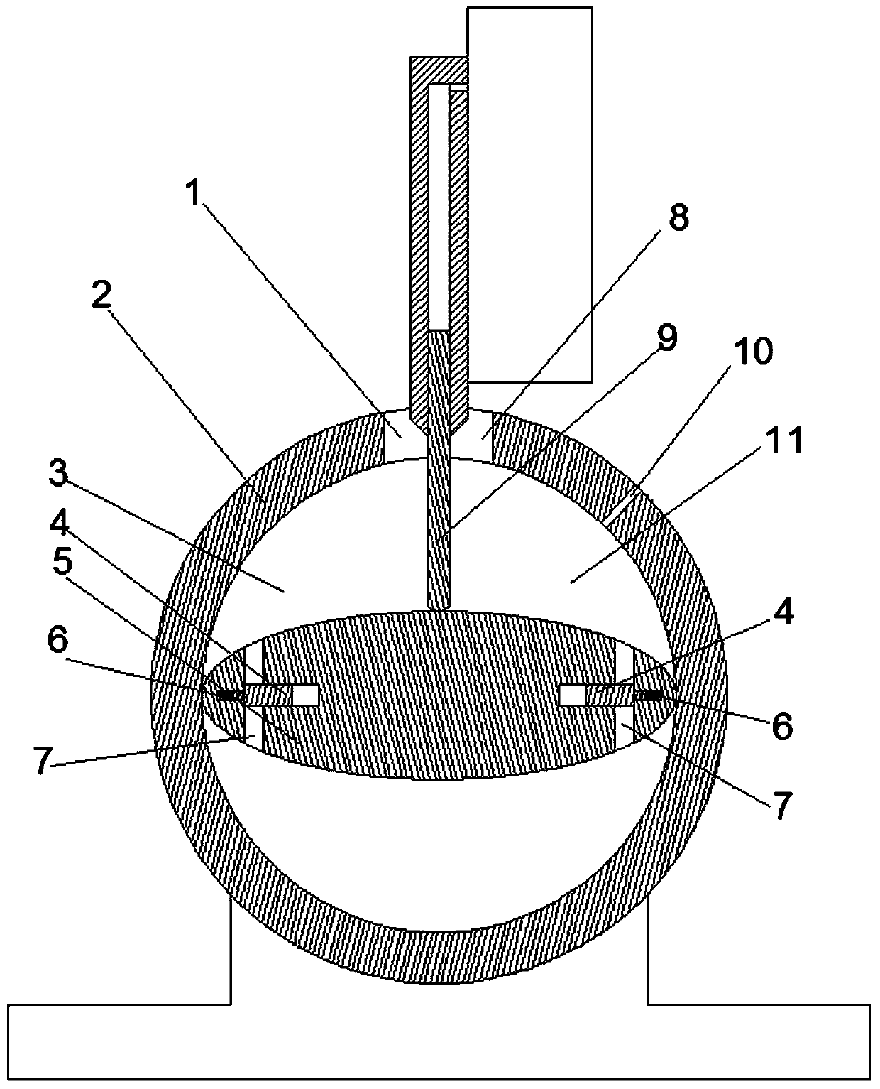
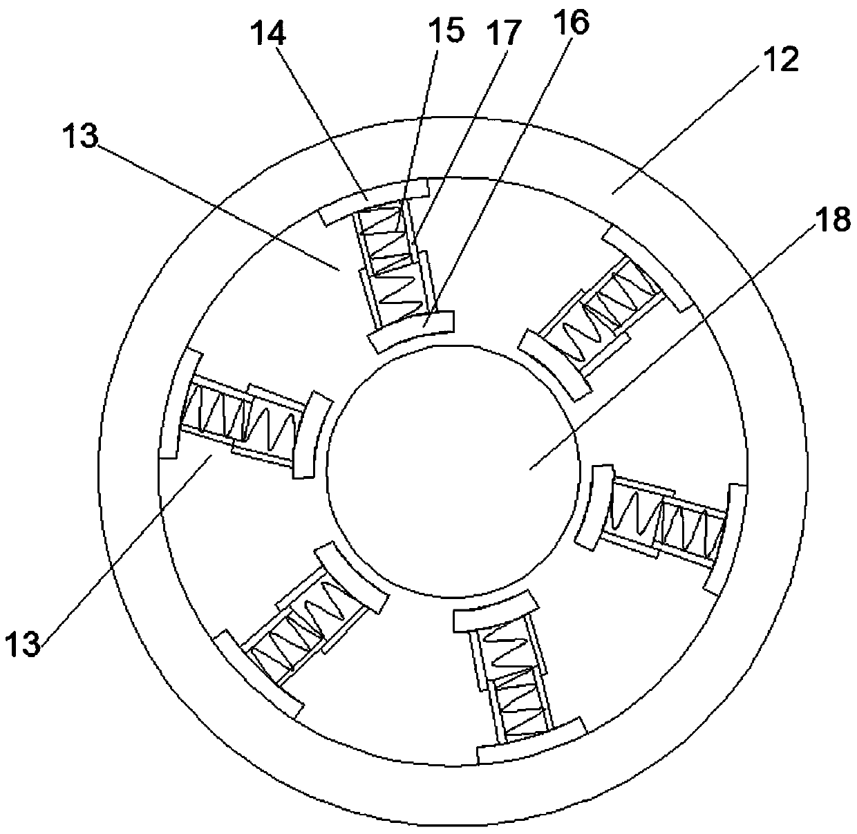
[0020] Examples of electric motor powertrains are Figure 1~6 Shown: includes motor 37 and pump 36, and pump 36 comprises the pump body 2 that has cylindrical hole inner chamber, is provided with the rotor 5 that rotation axis extends along the front-back direction, and cross-section is ellipse in the pump body 2, and the rotor 5 There are two tangent points between the cross section and the cylindrical inner hole. There is a hole on the pump body, and the guiding movement assembly at the hole has one end that slides and pushes with the outer peripheral surface of the rotor to separate the hole into a liquid inlet 8 and a liquid outlet. The partition 9 of 1, the inner cavity of the cylindrical hole is also separated by the partition 9 into a low-pressure chamber 11 communicating with the liquid inlet 8 and a high-pressure chamber 3 communicating with the liquid outlet 1, and the two ends of the rotor in the long diameter direction are provided with communication The oil guide ...


PUM


Abstract

The invention relates to a motor power assembly and a bearing block thereof. The motor power assembly comprises a motor, wherein the motor comprises the bearing block and a motor shaft; the bearing block comprises a frame-shaped body; at least one clamping unit is arranged on the frame-shaped body; each clamping unit in each pair of clamping units comprises a screw which is in threaded connection with the frame-shaped body; a clamping block which is used for clamping a corresponding bearing is rotatably arranged at the inner end of each screw; the screws of the clamping units in each pair of clamping units are coaxial and the directions of turning of threads of the screws are opposite; transmission holes which are coaxial with the screws are separately formed in the screws of the two clamping units of each pair of clamping units; and orifices of the transmission holes of each pair of clamping units are opposite. By the bearing block, the central position of a bearing cannot be changed when the screws are adjusted.

Description

technical field [0001] The invention relates to a motor power assembly and a bearing seat thereof. Background technique [0002] Chinese patent CN104901463B discloses "a motor end cover". The motor end cover includes an end cover body and a bearing seat arranged on the end cover body. The screw rods are rotatably equipped with clamping blocks at the inner ends of each screw rod, and the bearings matched with the motor shaft are clamped and fixed between the clamping blocks. When it is necessary to match motor shafts of different diameters, the corresponding bearings also need to be replaced. At this time, it is necessary to rotate and adjust each screw rod to adjust the distance between each clamping block to match the corresponding bearings. The existing problem of this kind of bearing seat is: the two screw rods in each pair are independent of each other during adjustment, which may cause one screw rod to be twisted half a turn more or the other screw rod to be turned hal...

Claims


Application Information

Patent Timeline
Patent Type & Authority Patents(China)
IPC IPC(8): H02K5/16H02K7/102H02K7/14H02K5/124F04C11/00
CPCF04C11/008H02K5/124H02K5/16H02K7/1023H02K7/14
Inventor 马来勋
Owner 上海拓泓机械科技有限公司
Why Eureka
Try Eureka