Forward extrusion uniform deformation die

A uniform deformation and positive extrusion technology, applied in the direction of metal extrusion dies, can solve the problems of unfavorable metal flow, uneven deformation of formed parts, etc., and achieve the effect of improving performance, improving metal dead zone, and improving uneven deformation

Active Publication Date: 2017-11-07
ZHONGBEI UNIV
View PDF5 Cites 2 Cited by
  • Summary
  • Abstract
  • Description
  • Claims
  • Application Information

AI Technical Summary

Problems solved by technology

[0003] Image 6 The flow of metal during the original punch extrusion process simulated for Deform. It can be seen from the figure that during the original punch extrusion process, the metal flow direction is always kept straight down, which is obviously not conducive to the flow of metal. Different degrees of metal "dead zone" will be generated at the corner of the die exit, resulting in uneven deformation of the formed part

Method used


Image

  • Forward extrusion uniform deformation die
  • Forward extrusion uniform deformation die
  • Forward extrusion uniform deformation die

Examples


Embodiment Construction

[0021] In order to make the object, technical solution and advantages of the present invention clearer, the present invention will be further described in detail below in conjunction with the accompanying drawings and specific embodiments. It should be understood that the specific embodiments described here are only used to explain the present invention, and are not intended to limit the present invention.

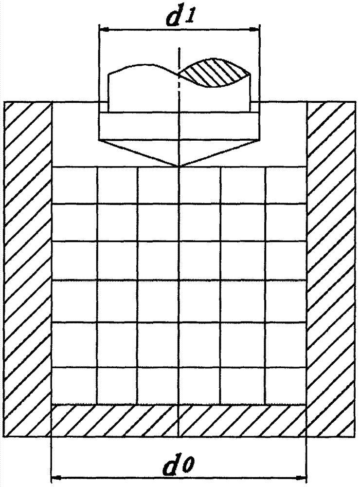
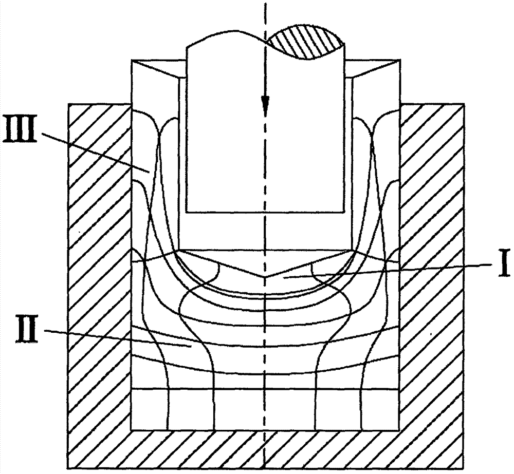
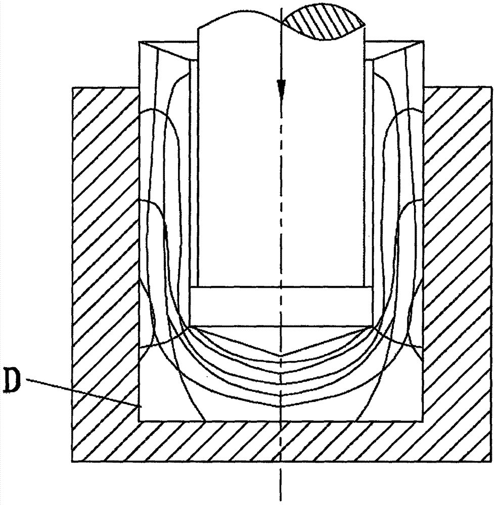
[0022] see Figure 2-Figure 5 , the specific embodiment adopts the following technical solutions: a positive extrusion uniform deformation die, which includes a punch body 1, a punch head 2, a groove 3 and an arched structure 4, and the punch head of the punch body 1 2 is provided with a groove 3 in the middle, the length of the groove 3 is equal to the diameter of the punch head 2, and an arched structure 4 is arranged in the middle of the groove 3, and the cross section of the arched structure 4 is arc-shaped. With this design, when the punch head 2 is in contact with t...


PUM


Abstract

The invention discloses a forward extrusion uniform deformation die and relates to the field of metal plasticity forming. A groove is formed in the middle of a male die head of a male die body; an arched structure is arranged in the middle of the groove; the cross section of the arched structure is in an arc shape; the length of the groove is equal to the diameter of the male die head; and the height of the arched structure is the same as the depth of the groove. Friction force between a male die and a billet is greatly reduced, and uniform flow of metal is promoted.

Description

technical field [0001] The invention relates to the field of metal plastic forming, in particular to a mold for promoting uniform deformation of positive extrusion. Background technique [0002] The grid changes in each stage of traditional forward extrusion are shown in Fig. 1. Fig. 1(a) shows the beginning state of forward extrusion, and Fig. 1(b) shows the change of mesh when the billet whose height is larger than the diameter enters a stable deformation state. At this time, the grid change inside the billet can be divided into three areas: the I area is the metal dead area, which is close to the end face of the punch and has a tapered shape. The size of the taper is determined by the friction between the end face of the punch and the blank. This part of the metal does not deform substantially. Zone II is a severe deformation zone. The blank flows sharply outward and upward in this area, and the cup-shaped part is mainly formed by this part of the metal flow. The axi...

Claims


Application Information

Patent Timeline
Patent Type & Authority Applications(China)
IPC IPC(8): B21C25/02B21C23/04
CPCB21C23/04B21C25/02
Inventor 张治民于建民白冰董贝贝王强郝红元程眉孟模
Owner ZHONGBEI UNIV
Why Eureka
Try Eureka