Dynamic flame simulating device

a flame simulating device and dynamic technology, applied in the field of electronic lighting, can solve the problems of inability to replace the illumination lamps used in the today's daily life, predetermined security risks, and extreme restrictions in the direction of sheet-like body swinging direction and amplitude,

Active Publication Date: 2016-07-12
GLOBAL RICH INVESTMENT CO LTD
View PDF13 Cites 9 Cited by
  • Summary
  • Abstract
  • Description
  • Claims
  • Application Information

AI Technical Summary

Benefits of technology

[0008]An object of the invention is to provide a dynamic flame simulating device having a suspending mode, which does not restrict the flame element, and an operation mode of driving a magnet to bounce repeatedly to make the swinging of the flame element more realistic and natural, thereby significantly improving the problem of the lighting product of the conventional simulated flame.
[0009]Another object of the invention is to provide a simple structure suitable for the mass production, thereby significantly decreasing the production cost.
[0011]Compared with the conventional product with the linear contact suspending mode, the invention uses the single-point contact suspending mode to effectively overcome the limitation of the swinging angle of the flame element, and decrease the contact friction generated so that the flame element swings more naturally, and the optimum dynamic beating effect of simulating the flame can be obtained. Furthermore, compared with the conventional product using the electric motor and having the cost that cannot be decreased, the invention utilizes the electromagnetic coil as the driving source, thereby effectively decreasing the material cost, and decreasing the electric energy consumption of the product in use so that the product can be used for a longer period of time. In addition, the periodic swinging problem of the flame element caused by the driving of the electric motor can be solved.
[0014]Preferably, the hooking portion comprises a connection section, which is tapered and gradually narrowed, wherein a free end of the connection section is bent upwards to form a hook for hanging the blind hole of the flame element, thereby decreasing the restriction of the swinging angle of the flame element.
[0015]Preferably, the upper base further has a limit through hole formed around the hook, wherein the flame element penetrates through the limit through hole to prevent the hooking of the blind hole of the flame element from failing.
[0019]Preferably, the bearing seat is connected to one end of a sub-frame, and the sub-frame has the other end connected to the upper base. The sub-frame may be used to properly adjust the distance between the second magnetic element and the first magnetic element, so that the repellent magnetic acting forces can achieve the optimum effect.

Problems solved by technology

In today's society, although conventional illumination tools, such as candles, oil lamps or the like, have been replaced by various electric lamps, the candles or the oil lamps still have conventional meanings and distinctive visual effects in some special occasions or special situations, and thus cannot be replaced by the illumination lamps used in the today's daily life.
However, the conventional lamps, such as candles, oil lamps or the like, are used for illumination by way of flame combustion, and have the predetermined security risks.
When the candles or oil lamps are upset due to the wind blowing or the artificial inadvertent touch, the ambient flammable objects tend to be ignited to cause the fire accident.
However, the lamp shade of such the flame lamp has the fixed shape, and the stable light source is formed after the flame lamp is turned on, and this effect is significantly different from the dynamic visual effect of the beating flame upon burning of the candle frame.
However, although the mounting of the iron wire through the hole can implement the swinging of the sheet-like body to a predetermined extent, the iron wire is fixed, and the swinging direction and amplitude of the sheet-like body are extremely restricted in order to prevent the sheet-like body and the driving mechanism from offsetting.
Thus, the flame lamp cannot simulate the perception of the dynamic flame, and is still significantly different from the naturally beating flame.

Method used


Image

  • Dynamic flame simulating device
  • Dynamic flame simulating device
  • Dynamic flame simulating device

Examples


Embodiment Construction

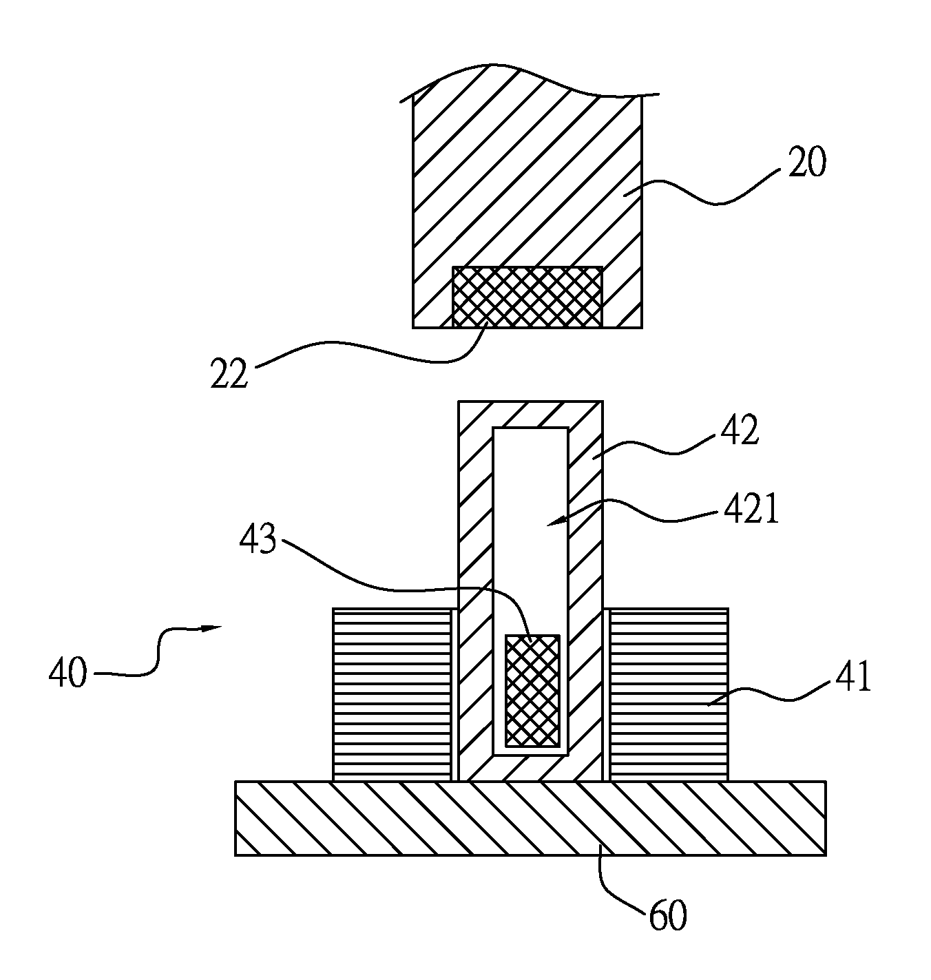
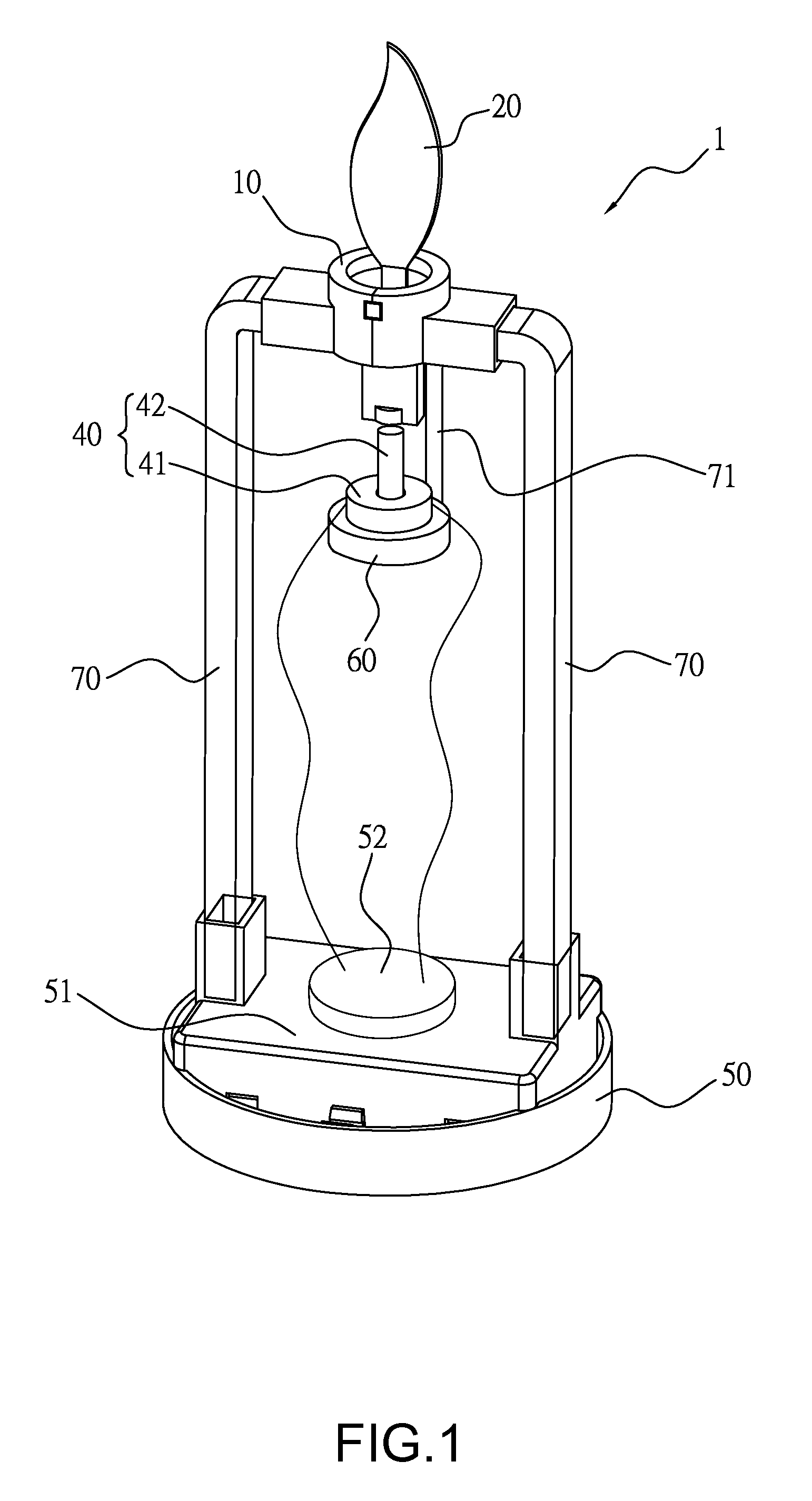
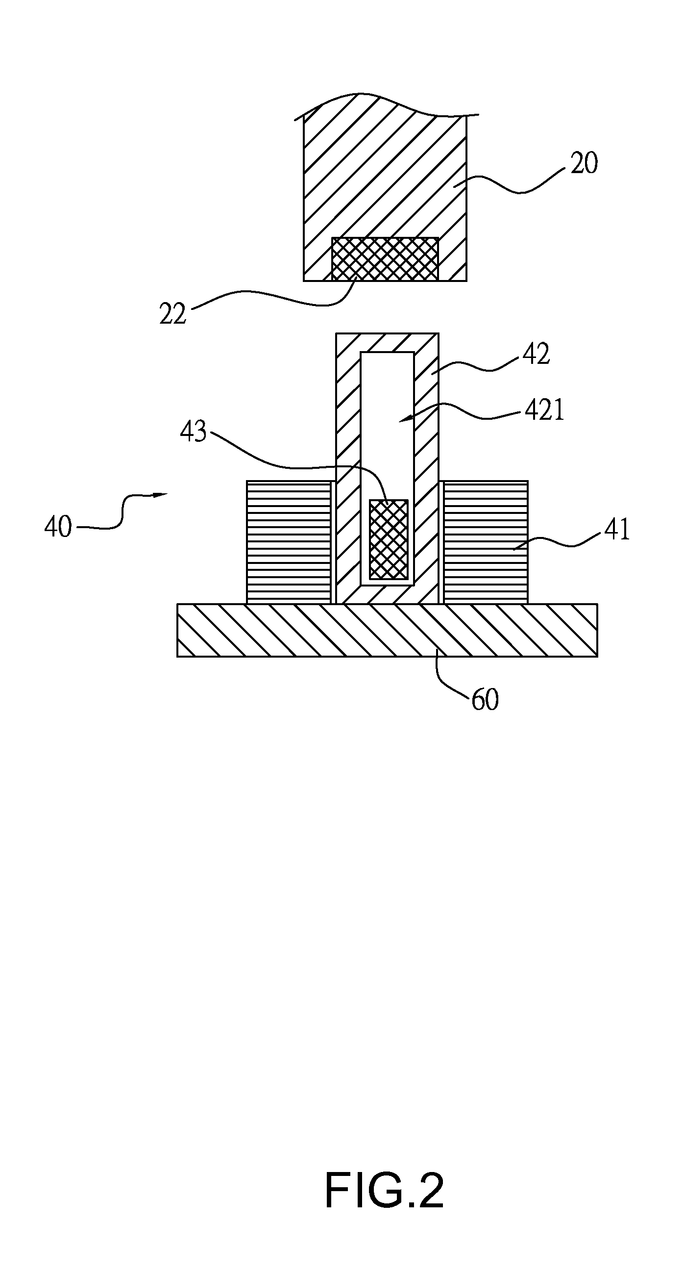
[0027]Referring to FIGS. 1 to 3, a dynamic flame simulating device 1 according to the embodiment of the invention mainly comprises an upper base 10, a flame element 20, a light source 30, a driving assembly 40, a lower base 50, a bearing seat 60, two main frames 70 and a sub-frame 71. The upper base 10 is connected to the lower base 50 through the two main frames 70, so that the upper base 10 is disposed above the lower base 50. The bearing seat 60 is connected to the upper base 10 through the sub-frame 71, and is disposed between the upper base 10 and the lower base 50. The flame element 20 and the light source 30 are disposed in the upper base 10, and the driving assembly 40 is disposed on the bearing seat 60.

[0028]Referring again to FIGS. 3 to 5, a horizontal surface of the upper base 10 is formed with a limit through hole 12, and a hooking portion 11 is disposed on one side of the limit through hole 12. The hooking portion 11 is made of a bent metal material, and has one end fix...


PUM


Abstract

A dynamic flame simulating device mainly comprises an upper base, a flame element suspended from the upper base, a light source providing light rays, and a driving assembly below the flame element. The driving assembly further comprises an electromagnetic coil and a second magnetic element, wherein the electromagnetic coil is powered on to drive the second magnetic element to bounce toward a first magnetic element on the bottom end of the flame element to generate repellent magnetic acting forces to make the flame element swing naturally and achieve the dynamic visual effect of the natural beating of the burning flame.

Description

BACKGROUND OF THE INVENTION[0001](1) Field of the Invention[0002]The invention relates to electronic lighting for simulating a candle frame, and more particularly to a dynamic flame simulating device capable of simulating a dynamic effect of a burning candle frame.[0003](2) Description of the Prior Art[0004]In today's society, although conventional illumination tools, such as candles, oil lamps or the like, have been replaced by various electric lamps, the candles or the oil lamps still have conventional meanings and distinctive visual effects in some special occasions or special situations, and thus cannot be replaced by the illumination lamps used in the today's daily life. For example, upon worshiping deities or ancestors, incense and candles are often used, and the beating fire on the candle is used to anchor the reminiscence on the ancestor and the endless longing to the posterity. Alternatively, in some occasions where specific atmospheres need to be created, the fire beating ...

Claims


Application Information

Patent Timeline
Patent Type & Authority Patents(United States)
IPC IPC(8): F21S10/04F21S6/00F21V23/00
CPCF21S10/046F21S6/001F21V23/00F21W2121/00
Inventor LAI, WEN-CHENG
Owner GLOBAL RICH INVESTMENT CO LTD
Why Eureka
Try Eureka