
Slurry-scraping equipment with preheating function

A technology of equipment and functions, applied in the field of scraping equipment with preheating function, can solve the problems of no preheating and shaping, the slurry cannot be cleaned in time, and the scraping effect is poor, and the effect of improving the scraping effect can be achieved.

Inactive Publication Date: 2017-11-07
CHANGXING DEHONG MACHINERY CO LTD
View PDF1 Cites 2 Cited by
  • Summary
  • Abstract
  • Description
  • Claims
  • Application Information

AI Technical Summary

Problems solved by technology

[0005] The purpose of the present invention is to aim at the deficiencies of the prior art, by arranging the scraping part to scrape the warp yarn while transporting and setting the cleaning part in the scraping part to clean the roller after scraping, so as to complete the cleaning of the roller. The wheel is dried in the drying part to overcome the poor scraping effect during the scraping process, the slurry is easy to accumulate in one place, the scraped slurry cannot be cleaned in time, and the warp yarn that has been scraped is not equipped to quickly A warm-up question

Method used


Image

  • Slurry-scraping equipment with preheating function
  • Slurry-scraping equipment with preheating function
  • Slurry-scraping equipment with preheating function

Examples


Embodiment 1

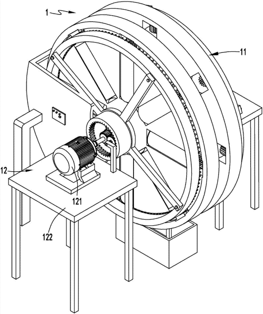
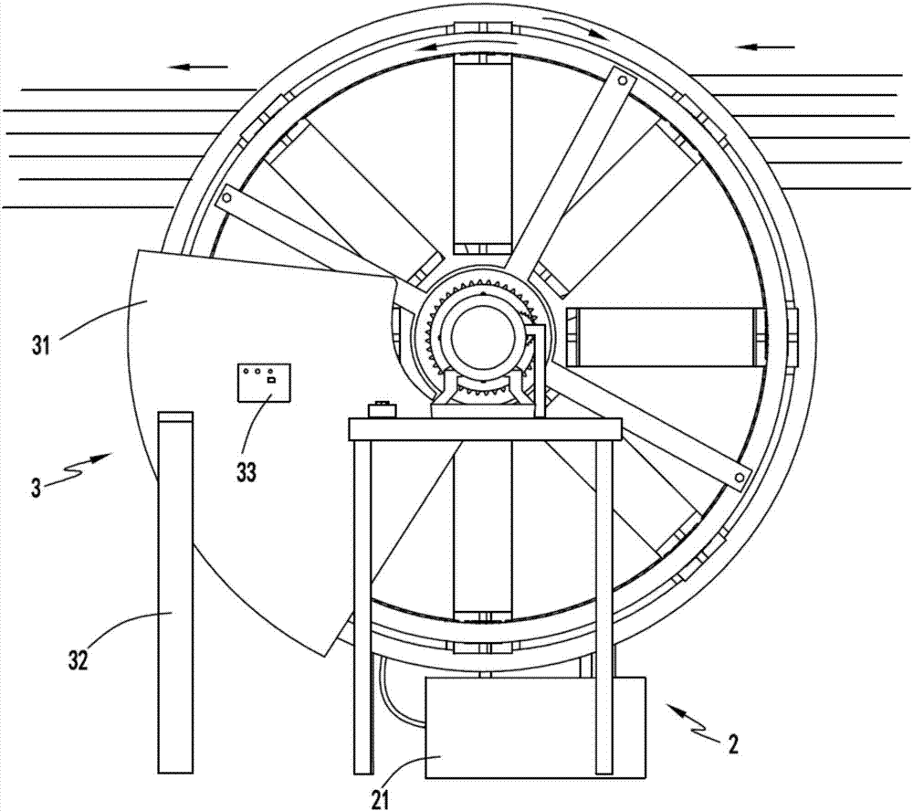
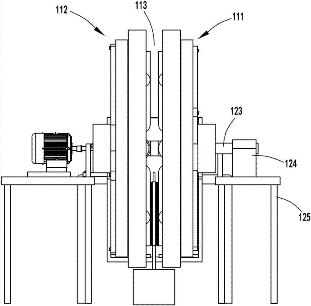
[0035] like figure 1 , figure 2 , image 3 , Figure 4 , Figure 5 , Image 6 , Figure 7 As shown in Figure 8, a squeegee device with a preheating function includes a squeegee part 1, and the squeegee part 1 includes a squeegee mechanism 11 and a drive mechanism 12 arranged on one side of the squeegee mechanism 11. The driving mechanism 12 is used to drive the squeegee mechanism 11 to squeegee and pre-dry the warp yarns passing through while rotating;

[0036] The cleaning part 2, the cleaning part 2 is arranged in the scraping mechanism 11, the cleaning part 2 includes a water collecting tank 21 and a cleaning mechanism 22 arranged above the water collecting tank 21, and the cleaning mechanism 22 is used to complete the cleaning in the scraping mechanism 11. During the process of scraping and continuing to rotate, spray water to clean the surface;

[0037] And a drying part 3, the drying part 3 is arranged on the rotation path of the squeegee mechanism 11 and behind ...

Embodiment 2

[0047] like figure 1 , figure 2 , image 3 , Figure 4 , Figure 5 , Image 6 , Figure 7 and Figure 8 As shown, the components that are the same as or corresponding to those in the first embodiment are marked with the corresponding reference numerals in the first embodiment. For the sake of simplicity, only the differences from the first embodiment will be described below. The difference between the second embodiment and the first embodiment is that the cleaning mechanism 22 includes a conduit 221 communicating with the inside of the water collecting tank 21 and a cleaning member 222 communicating with the conduit, and the cleaning member 222 includes a 21 on the cleaning plate 2221, the surface of the cleaning plate 2221 is provided with several brushes 2222 and the interval between the brushes 2222 and the brushes 2222 is provided with several water spray holes 2223, and the brushes 2222 are used for scraping Clean the slurry slag on the roller 11132, and the water...


PUM


Abstract

The invention relates to slurry-scraping equipment with a preheating function. The slurry-scraping equipment comprises a slurry-scraping part, a cleaning part and a drying part; the slurry-scraping part comprises a slurry-scraping mechanism and a driving mechanism arranged on one side of the slurry-scraping mechanism; the cleaning part is arranged in the slurry-scraping mechanism and comprises a water collecting tank and a cleaning mechanism arranged above the water collecting tank; the drying part is arranged on the rotation path of the slurry-scraping mechanism and at the rear portion of the cleaning part. The slurry-scraping equipment with the preheating function solves the problems that the slurry-scraping effect in the slurry-scraping process is poor, slurry is easy to accumulate in one place, scraped slurry is not cleaned up in time, and warp yarn cannot be quickly preheated and shaped after slurry scraping is finished.

Description

technical field [0001] The invention relates to the technical field of textile squeegee equipment, in particular to a squeegee equipment with a preheating function. Background technique [0002] In the fabric pre-treatment technology, the fabric needs to be dried in a dryer after sizing. If the sizing of the fabric is uneven, the thickness of the fabric will be uneven after drying, which will affect the product quality. Therefore, uniform sizing of the fabric is very important, and usually the fabric After the dipping, the excess slurry is squeezed out by the paddle, but as we all know, the paddle has uneven rolling pressure, so the fabric sizing will inevitably cause uneven sizing of the fabric through the paddle after sizing. [0003] Authorized notification number CN203393462U is a Chinese utility model patent, which discloses a scraper device, which is composed of a support, a cross brace, an adjustment rod, a cylinder, a scraper rod, etc., and the two ends of the cross ...

Claims


Application Information

Patent Timeline
Patent Type & Authority Applications(China)
IPC IPC(8): D06B1/12D06B23/30D06C7/02
CPCD06B1/12D06B23/30D06C7/02
Inventor 乔海美
Owner CHANGXING DEHONG MACHINERY CO LTD
Learn More