
A seepage water blocking structure and heat exchange structure

A water blocking and seepage technology, applied in the field of geothermal systems, can solve problems such as failure to work normally, and achieve the effect of reducing the seepage velocity

Inactive Publication Date: 2020-04-28
JILIN JIANZHU UNIVERSITY
View PDF6 Cites 0 Cited by
  • Summary
  • Abstract
  • Description
  • Claims
  • Application Information

AI Technical Summary

Problems solved by technology

[0004] The purpose of the present invention is to provide a seepage water blocking structure to improve the seepage velocity of the existing heat exchange structure in the soil greater than 4×10 -7 The problem of not working properly at m / s
[0005] The object of the present invention is also to provide a heat exchange structure, to improve the seepage velocity of the existing heat exchange structure in the soil greater than 4 × 10 -7 The problem of not working properly at m / s

Method used


Image

  • A seepage water blocking structure and heat exchange structure
  • A seepage water blocking structure and heat exchange structure
  • A seepage water blocking structure and heat exchange structure

Examples


Embodiment 1

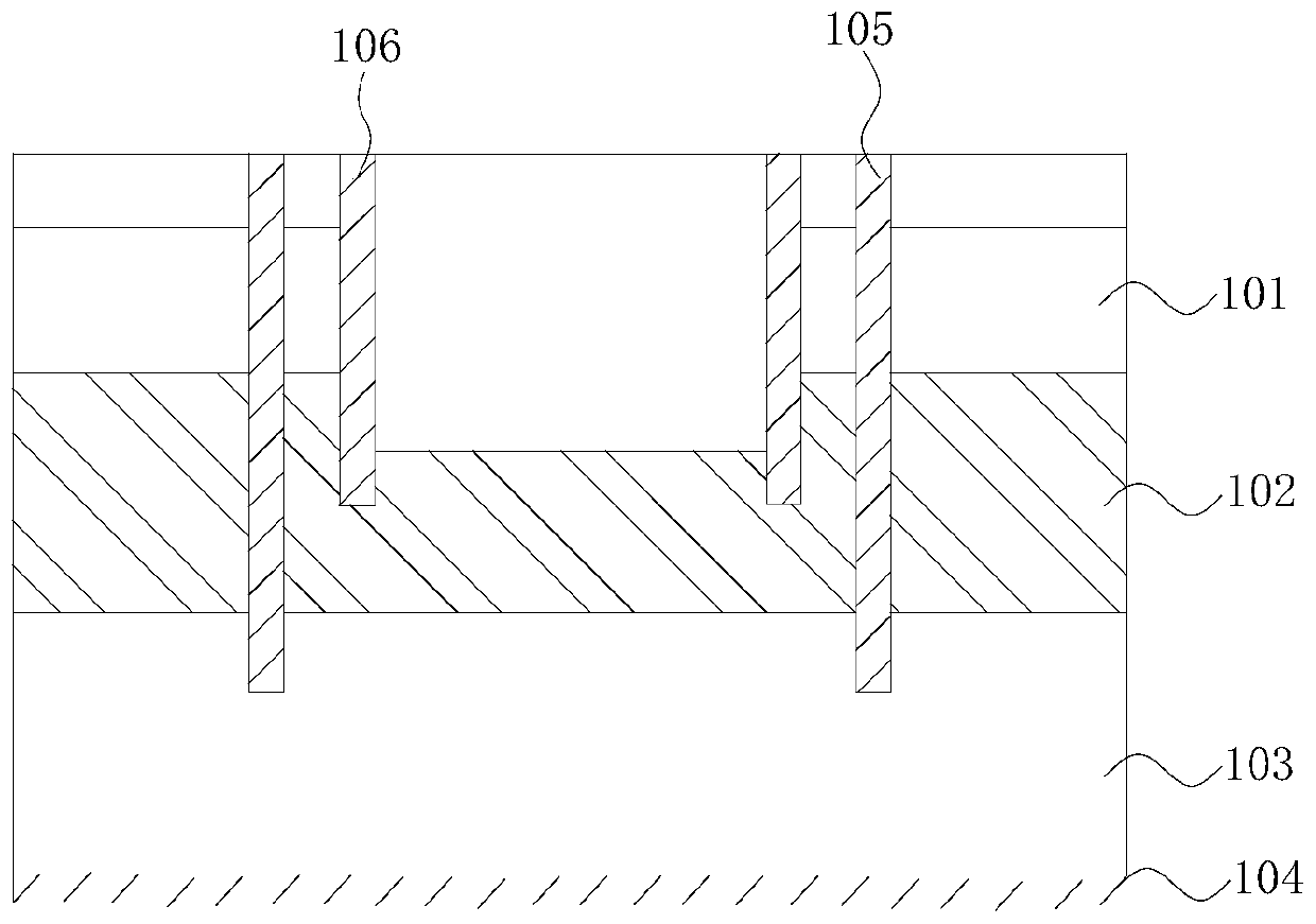
[0054] refer to figure 1 and figure 2 , the present embodiment provides a seepage water blocking structure for installation on a terrain, including a precipitation well 105 and an annular enclosure structure 106, and the terrain includes a submerged layer 101 and an aquitard 102 arranged from top to bottom , the confined water layer 103 and the water-resistant layer 104, the precipitation well 105 passes through the submerged layer 101 and the aquitard 102 to communicate with the confined water layer 103, and the enclosure structure 106 is installed outside the precipitation well 105, and the enclosure structure 106 is connected to the The precipitation wells 105 are arranged at intervals, and the bottom of the enclosure structure is installed on the aquitard 102 .

[0055] The seepage and water blocking structure provided in this embodiment utilizes the enclosure structure 106 and the dewatering well 105, and the seepage velocity is greater than 4×10 -7 The m / s soil is tra...

Embodiment 2

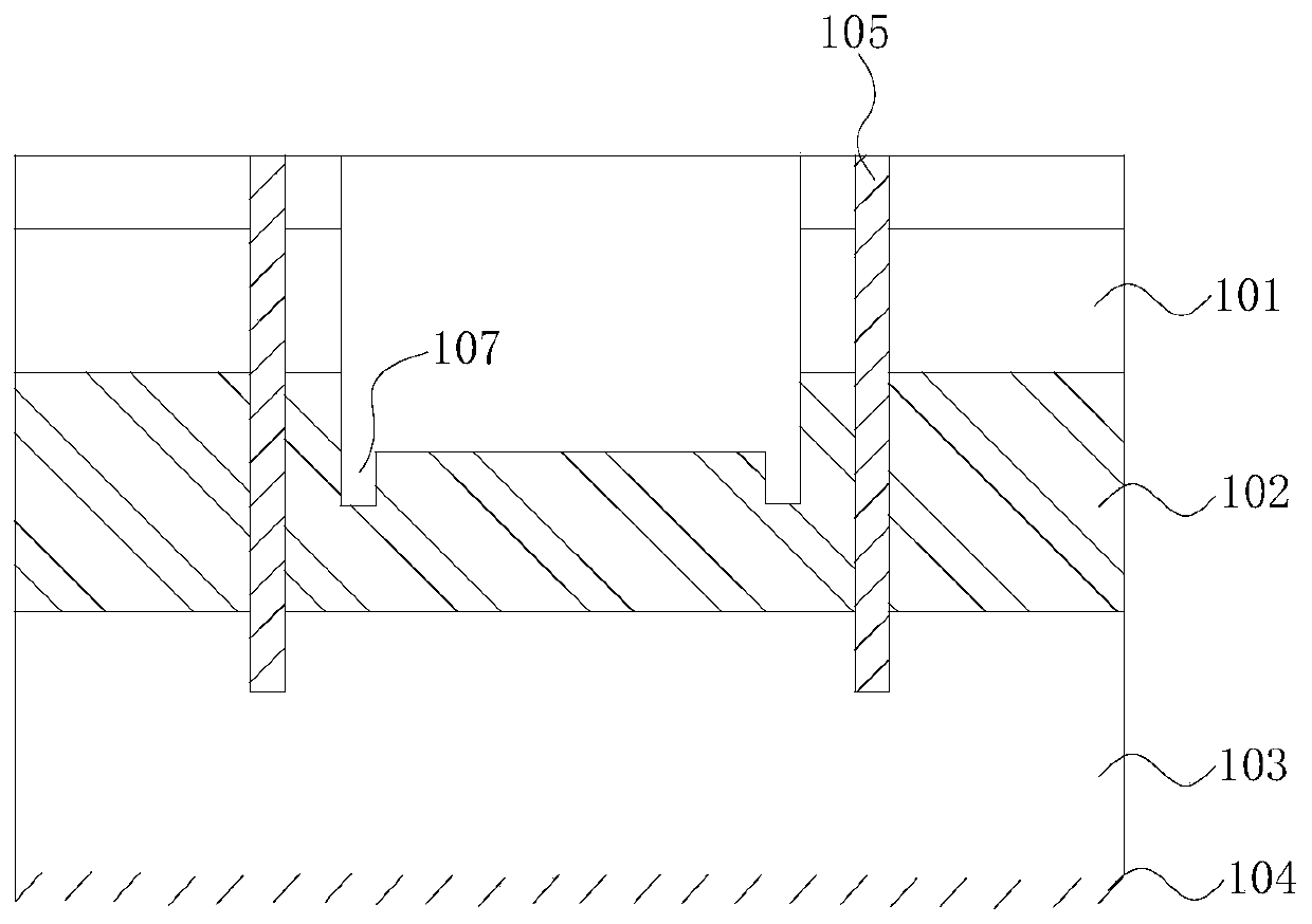
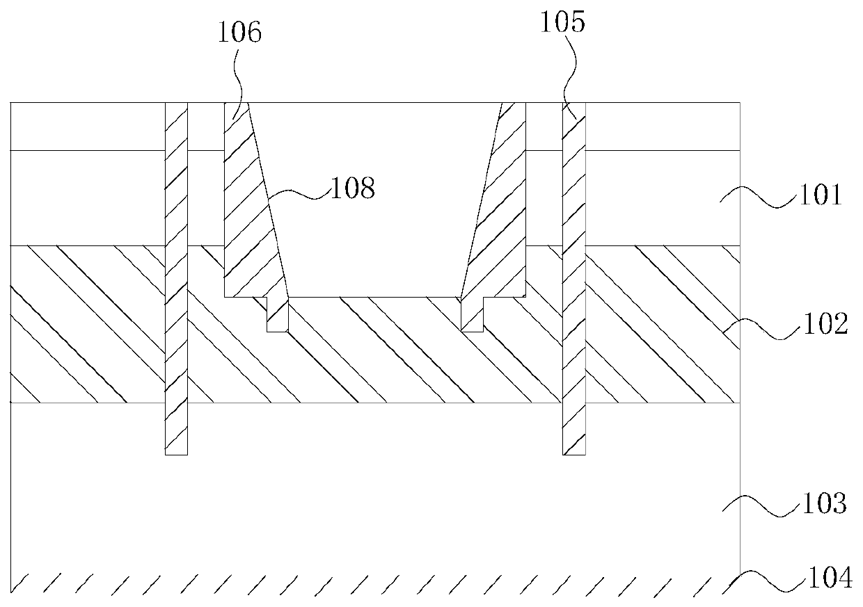
[0062] refer to Figure 3 to Figure 5 , this embodiment also provides a seepage water blocking structure, this embodiment is a further improvement on the basis of the technical solution of embodiment 1, the technical solution described in embodiment 1 is also applicable to this embodiment, embodiment 1 has The disclosed technical solutions will not be described repeatedly.

[0063] Specifically, the difference between this embodiment and Embodiment 1 is that the cross-sectional area of ​​the top of the through hole of the seepage water blocking structure provided by this embodiment is larger than the cross-sectional area of ​​the bottom of the through hole.

[0064] The structure that the cavity is large at the top and small at the bottom can greatly improve the heat transfer efficiency, thereby improving the working efficiency of the energy pile 112 .

[0065] The enclosure structure 106 is provided with a slope 108 , and the slope 108 is inclined inwardly from the top of th...

Embodiment 3

[0068] refer to Figure 6 and Figure 7 , this embodiment also provides a seepage water blocking structure, this embodiment is a further improvement on the basis of the technical solution of embodiment 1, the technical solution described in embodiment 1 is also applicable to this embodiment, embodiment 1 has The disclosed technical solutions will not be described repeatedly.

[0069] Specifically, the difference between this embodiment and Embodiment 1 is that the enclosure structure 106 provided in this embodiment also includes a mounting piece 111, the installation piece 111 is located between the inclined surface 108 and the block 109, and the installation piece 111 is along the enclosure structure 106 The circumference is circular.

[0070] When excavating the groove 107 on the impermeable layer 102, some defects in the structure of the groove 107 can be avoided. The setting of the mounting sheet 111 can cover these defects, avoiding the impact of energy due to potholes ...


PUM


Abstract

The invention provides a seepage water blocking structure and a heat exchange structure, and belongs to the field of geothermal systems. The seepage water blocking structure is used for being installed on a terrain and comprises a precipitation well and an annular enclosure structure, the terrain comprises a phreatic layer, an aquitard, an artesian aquifer and an aquiclude which are arranged from top to bottom, the precipitation well penetrates through the phreatic layer and the aquitard and communicates with the artesian aquifer, the enclosure structure is arranged in the precipitation well and is in spacing arrangement with the precipitation well, and the bottom of the enclosure structure is installed at the aquitard. The heat exchange structure comprises an energy pile and the seepage water blocking structure mentioned above, and the energy pile is installed in the enclosure structure. According to the seepage water blocking structure, the enclosure structure and the precipitation well are utilized to transform soil with a seepage speed of more than 4*10<-7>m / s, the enclosure structure and the precipitation well are in spacing arrangement, the seepage speed of the soil in the precipitation well is greatly reduced, and thus the soil can store enough energy to supply the energy pile.

Description

technical field [0001] The invention relates to the field of geothermal systems, in particular to a seepage water blocking structure and a heat exchange structure. Background technique [0002] The ground source heat pump system uses the underground soil as a low-grade cold and heat source. Since the temperature of the underground soil is relatively constant, and the temperature range is very suitable for the efficient operation of the heat pump unit, it can effectively reduce the energy consumption of the unit operation and contribute to building energy conservation and emission reduction. positive contribution, however, when the seepage velocity of the soil is greater than 4×10 -7 m / s can no longer store heat normally, especially when the seepage velocity is greater than 1×10 -6 m / s, it is completely unable to store heat. [0003] The inventor found in the research that the existing heat exchange structure has at least the following disadvantages: the seepage velocity of...

Claims


Application Information

Patent Timeline
Patent Type & Authority Patents(China)
IPC IPC(8): F25B30/06
CPCF25B30/06Y02E10/10
Inventor 赵嵩颖秦佳琦赵松源张喜明姜长风龚建博郑浩男
Owner JILIN JIANZHU UNIVERSITY
Learn More