
Abutment separator

A separator and abutment technology, applied in medical science, dental prosthetics, dental implants, etc., can solve problems such as irreparable, abutment replacement, trauma and pain of patients, etc., and achieve the elimination of psychological burden, reasonable structure and convenient operation Effect

Active Publication Date: 2017-11-10
浙江广慈医疗器械有限公司
View PDF7 Cites 0 Cited by
  • Summary
  • Abstract
  • Description
  • Claims
  • Application Information

AI Technical Summary

Problems solved by technology

[0003] At present, there is no scientific, reasonable, simple and convenient instrument for separating the abutment on the implant without any damage. The abutment on the implant is often separated by tapping with a hammer sideways. However, there are the following three methods in this way: fatal flaw:
[0004] 1. Due to the cooperation between the abutment and the implant, the way the hammer strikes the abutment sideways will transmit the percussion force to the implant, which will easily cause the damage of the osseointegration of the implant;
[0005] 2. The method of sideways tapping with the hammer cannot 100% ensure the separation of the abutment;
[0006] 3. The lateral knocking of the hammer is easy to cause loose or broken damage to the abutment and the implant itself, resulting in the replacement of the abutment or irreparable, requiring re-planting, which brings greater trauma and pain to the patient

Method used


Image

  • Abutment separator
  • Abutment separator
  • Abutment separator

Examples


Embodiment Construction

[0033] The present invention will be described in further detail below in conjunction with the accompanying drawings and specific embodiments.

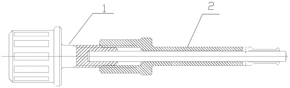
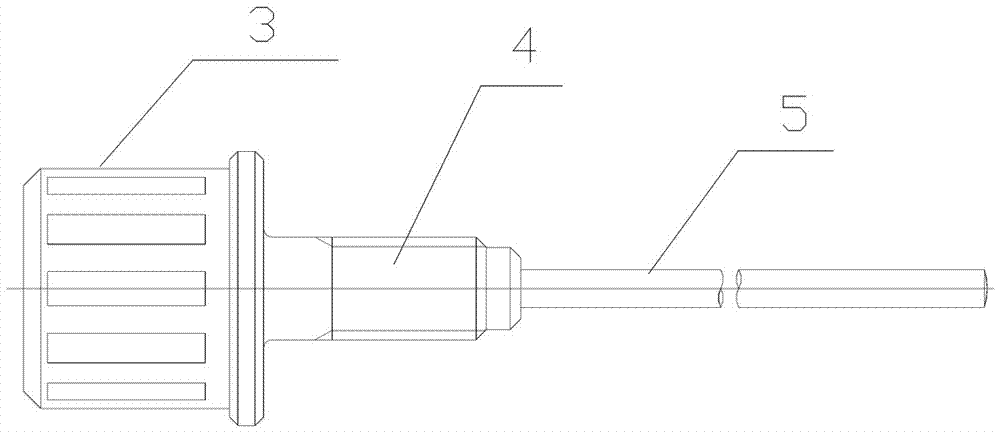
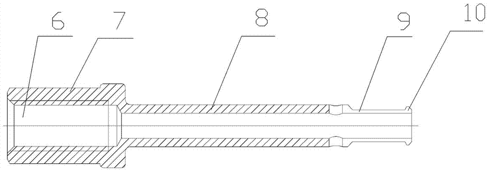
[0034] like figure 1 , 2 , 3, 4, 5, 6, 7, and 8, an abutment separator includes an elastic sleeve 2 and a separation rod 1 that can be inserted into the elastic sleeve 2 . like image 3 , 4 As shown, the elastic sleeve includes a tubular sleeve 8, the front end of the sleeve extends forward and is provided with elastic sheets 14 separated from each other, the ends of the elastic sheets are respectively provided with barbs 10, and there are four elastic sheets. The width increases sequentially in the circumferential direction, and the elastic sheet is surrounded to form an elastic sleeve 9, and the elastic sleeve formed by the elastic sheet is provided with a taper. The outer diameter and thickness of the sleeve 8 are larger than the outer diameter and thickness of the elastic sleeve 9 . The rear end of the pipe sleeve is provided...


PUM


Abstract

The invention relates to an abutment separator. The abutment separator comprises an elastic cannula and a separating rod, the front end of a cannular bush of the elastic cannular extends forwards to form elastic pieces, inverted hooks are arranged at the ends of the elastic pieces respectively, the elastic pieces form an elastic bush in a surrounding mode, a cannular bush base is arranged at the rear end of the cannular bush, a base inner hole is formed in the cannular bush base, and the separating rod comprises an ejector rod capable of being inserted into the cannular bush, a thread portion arranged at the upper end of the ejector rod and a hand wheel portion arranged at the upper end of the thread portion. The ejector rod is inserted into the cannular bush and extends out from the elastic bush, the separating rod is connected with the base inner hole through the thread portion in a threaded mode, and the ejector rod is screwed tightly along with a thread and further extends out from the elastic sleeve. The special separator is used for separating an abutment from a dental implant and operated conveniently, can separate the abutment from the dental implant easily, avoids damage to the abutment and the dental implant by hammer beating, also eliminates psychological burden for medical workers in the installation process of the abutment, and is reasonable in structure and convenient to operate.

Description

technical field [0001] The invention relates to an auxiliary tool for separating an abutment from a dental implant. Background technique [0002] The abutment separator is a device used to replace the abutment when the implant is "survived" during installation and commissioning, and to take out the abutment when the crown is loose and uncomfortable after the crown restoration. Since the abutment and the implant are fitted with a Moss taper, once fitted, the implant and the abutment are difficult to separate. [0003] At present, there is no scientific, reasonable, simple and convenient instrument for separating the abutment on the implant without any damage. The abutment on the implant is often separated by tapping with a hammer sideways. However, there are the following three methods in this way: fatal flaw: [0004] 1. Due to the cooperation between the abutment and the implant, the way the hammer strikes the abutment sideways will transmit the percussion force to the im...

Claims


Application Information

Patent Timeline
Patent Type & Authority Applications(China)
IPC IPC(8): A61C8/00
CPCA61C8/0089A61C2204/00
Inventor 徐仲棉徐益波张立法
Owner 浙江广慈医疗器械有限公司
Learn More