
X-ray based cut block positioning jig

一种照片、特定部位的技术,应用在医药科学、骨钻导引、手术等方向,能够解决昂贵、费时等问题

Inactive Publication Date: 2017-11-14
BIOMET MFG CORP
View PDF3 Cites 1 Cited by
  • Summary
  • Abstract
  • Description
  • Claims
  • Application Information

AI Technical Summary

Problems solved by technology

The process is expensive and time-consuming

Method used


Image

  • X-ray based cut block positioning jig
  • X-ray based cut block positioning jig
  • X-ray based cut block positioning jig

Examples


Embodiment Construction

[0020] Example embodiments will now be described more fully with reference to the accompanying drawings.

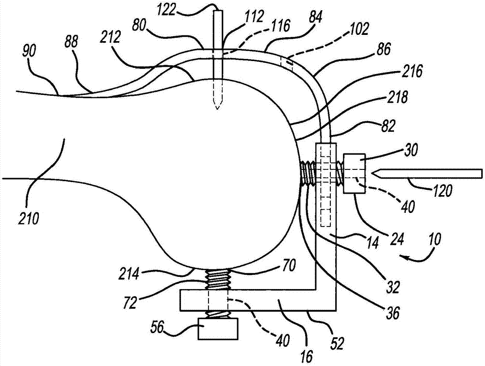
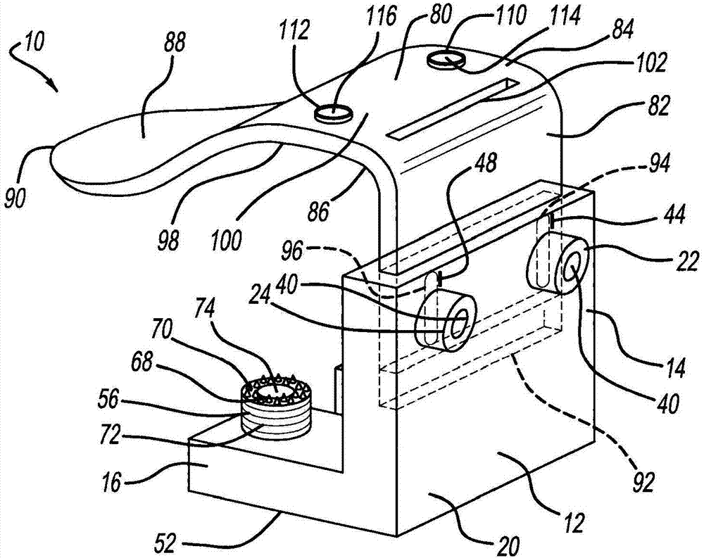
[0021] initial reference figure 1 with 2 , generally at 10 illustrates a femoral positioning jig according to the present teachings. The femur positioning jig 10 is configured to position the cutting die on the femur in preparation for the femur to receive the implant. For example, as described in detail herein, the femoral positioning jig 10 is reusable and adjustable to match the patient's anatomy based on the radiograph image. The femoral positioning jig 10 can be used in total knee replacement surgery, or in revision surgery.

[0022] The femoral positioning jig 10 generally includes a femoral base 12 having a first or distal portion 14 and a second or posterior portion 16 . The distal portion 14 and the posterior portion 16 can be at any suitable angle relative to each other, such as a right angle as illustrated. Femoral base 12 can be made of any suitable rigid...


PUM


Abstract

A cut block positioning jig includes a first alignment member, a second alignment member, and both first and second guide members. The first alignment member is movable towards and away from a patient's bone to which the positioning jig is mounted to arrange the jig at a predetermined position relative to the bone based on X-rays of the patient. The second alignment member is movable towards and away from the bone to arrange the jig at the predetermined position relative to the bone. The first and second guide members are configured to direct cut block support members to the bone to couple a cut block to the bone, thus providing the bone with patient-specific cuts.

Description

[0001] This application is a divisional application of an invention patent application with an application date of August 13, 2014, an application number of 201480054252.0, and an invention title of "Cutting Die Positioning Fixture Based on X-ray Photos". technical field [0002] The invention relates to a positioning fixture for a cutting mold used for cutting bones. Background technique [0003] This section provides background information related to the present invention which is not necessarily prior art. [0004] To prepare the bone to receive the implant, the bone is often cut using cutting dies. Die guides or positioning jigs can be used to set the correct position of the cutting die. The cutting die guide can be custom designed to fit a specific patient's bone and set the position of the cutting die based on the patient's specific anatomy. Such custom cutting die guides are often based on timely and expensive imaging modalities such as CT and MRI imaging. For exam...

Claims


Application Information

Patent Timeline
Patent Type & Authority Applications(China)
IPC IPC(8): A61B17/15A61B17/17
CPCA61B17/154A61B17/155A61B17/157A61B17/1703A61B17/1764A61B2017/568A61B2034/108
Inventor B·乌特格南特R·梅茨格
Owner BIOMET MFG CORP
Features
  • Generate Ideas
  • Intellectual Property
  • Life Sciences
  • Materials
  • Tech Scout
  • Unparalleled Data Quality
  • Higher Quality Content
  • 60% Fewer Hallucinations
Learn More