
Punching machine for vehicle plastic trims

A punching machine and plastic technology, applied in metal processing and other directions, can solve the problems of inability to achieve rapid punching equipment height, poor punching effect of punching machine, etc., and achieve the effect of simple structure, fast and efficient punching, and convenient operation.

Inactive Publication Date: 2017-11-17
寿光市煜盛汽车配件有限公司
View PDF5 Cites 0 Cited by
  • Summary
  • Abstract
  • Description
  • Claims
  • Application Information

AI Technical Summary

Problems solved by technology

[0003] The purpose of the present invention is to solve the shortcomings existing in the prior art, such as: the punching machine of automobile plastic trim can not realize the height of fast punching equipment, thus making the punching effect of the whole punching machine not good, and proposes a kind of automobile Punching machine for plastic trim

Method used

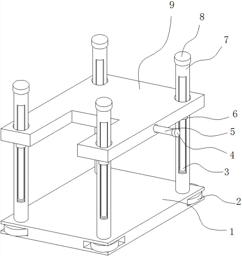
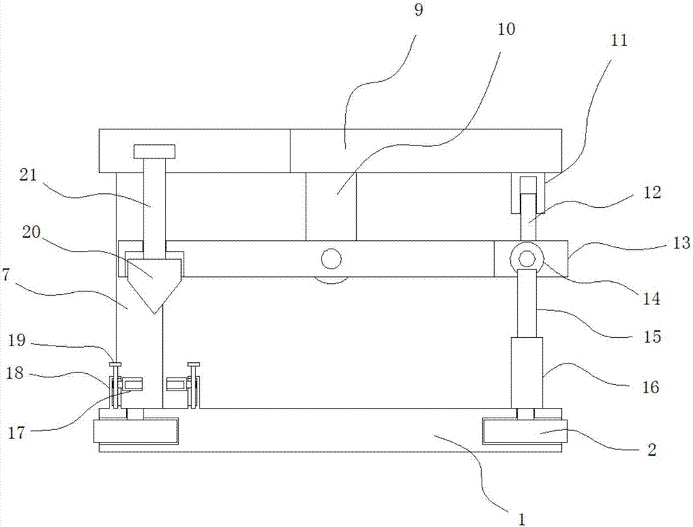
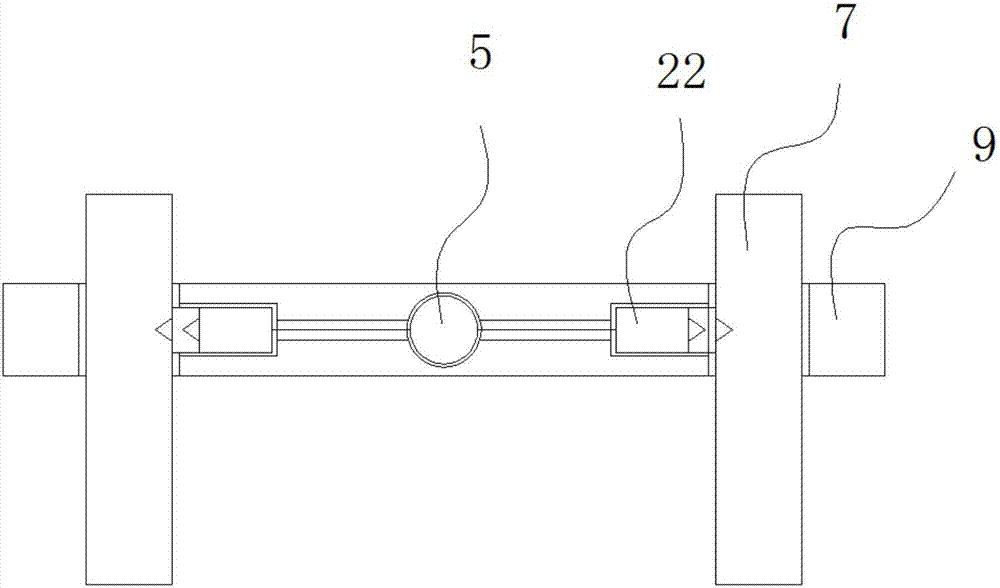

Image

  • Punching machine for vehicle plastic trims
  • Punching machine for vehicle plastic trims
  • Punching machine for vehicle plastic trims

Examples


Embodiment Construction

[0017] The following will clearly and completely describe the technical solutions in the embodiments of the present invention with reference to the accompanying drawings in the embodiments of the present invention. Obviously, the described embodiments are only some, not all, embodiments of the present invention.

[0018] In describing the present invention, it should be understood that the terms "upper", "lower", "front", "rear", "left", "right", "top", "bottom", "inner", " The orientation or positional relationship indicated by "outside", etc. is based on the orientation or positional relationship shown in the drawings, and is only for the convenience of describing the present invention and simplifying the description, rather than indicating or implying that the referred device or element must have a specific orientation, so as to Specific orientation configurations and operations, therefore, are not to be construed as limitations on the invention.

[0019] refer to Figure ...


PUM


Abstract

The invention discloses a punching machine for vehicle plastic trims. The punching machine comprises a baseplate, and a mounting plate positioned above the baseplate; support columns are arranged at four corners above the baseplate; mounting ports are formed in the mounting plate; the support columns penetrate through the mounting ports, and are connected with sealing blocks; rotating grooves are formed in four corners of the baseplate; first rotating blocks are arranged in the rotating grooves; locking rods are arranged on one sides of the first rotating blocks; one ends, far from the first rotating blocks, of the locking rods penetrate through the baseplate, and are connected with the support columns; a support rod is arranged on the bottom surface of the mounting plate; one end, far from the mounting plate, of the support rod is rotationally connected with a rotating plate; a mounting groove is formed in one end of the rotating plate; a rotating shaft is rotationally connected into the mounting groove; and a cylinder is mounted above the baseplate. The whole rotating plate can move to one side; then, an impact can quickly punch objects to be machined to realize quick and efficient punching; and the invention provides the punching machine for the vehicle plastic trims.

Description

technical field [0001] The invention relates to the technical field of processing equipment for automotive plastic trims, in particular to a punching machine for automotive plastic trims. Background technique [0002] Automotive plastic trims have the function of decorating and beautifying the car, and the quality of its decorative effect directly affects the internal and external image of the car. According to the actual situation of the car, in line with the principles of beauty, coordination, invention and safety, the decorative parts should be selected in a targeted manner to ensure the decorative effect. However, the current punching machines for plastic decorative parts of automobiles cannot achieve the height of fast punching equipment. Thereby the stamping effect of whole stamping machine is not good, influences the user to the processing of automobile plastic trim. Contents of the invention [0003] The purpose of the present invention is to solve the shortcoming...

Claims


Application Information

Patent Timeline
Patent Type & Authority Applications(China)
IPC IPC(8): B26F1/02B26D7/02
CPCB26D7/02B26F1/02
Inventor 项孝泓
Owner 寿光市煜盛汽车配件有限公司
Learn More