Spreading table with adjustable width
An adjustable and width technology, applied in the field of spreading tables, can solve the problems of table board width deviation and inability to use normally, and achieve the effects of reducing floor space, enhancing stability and ensuring synchronization
- Summary
- Abstract
- Description
- Claims
- Application Information
AI Technical Summary
Problems solved by technology
Method used
Image
Examples
Embodiment 1
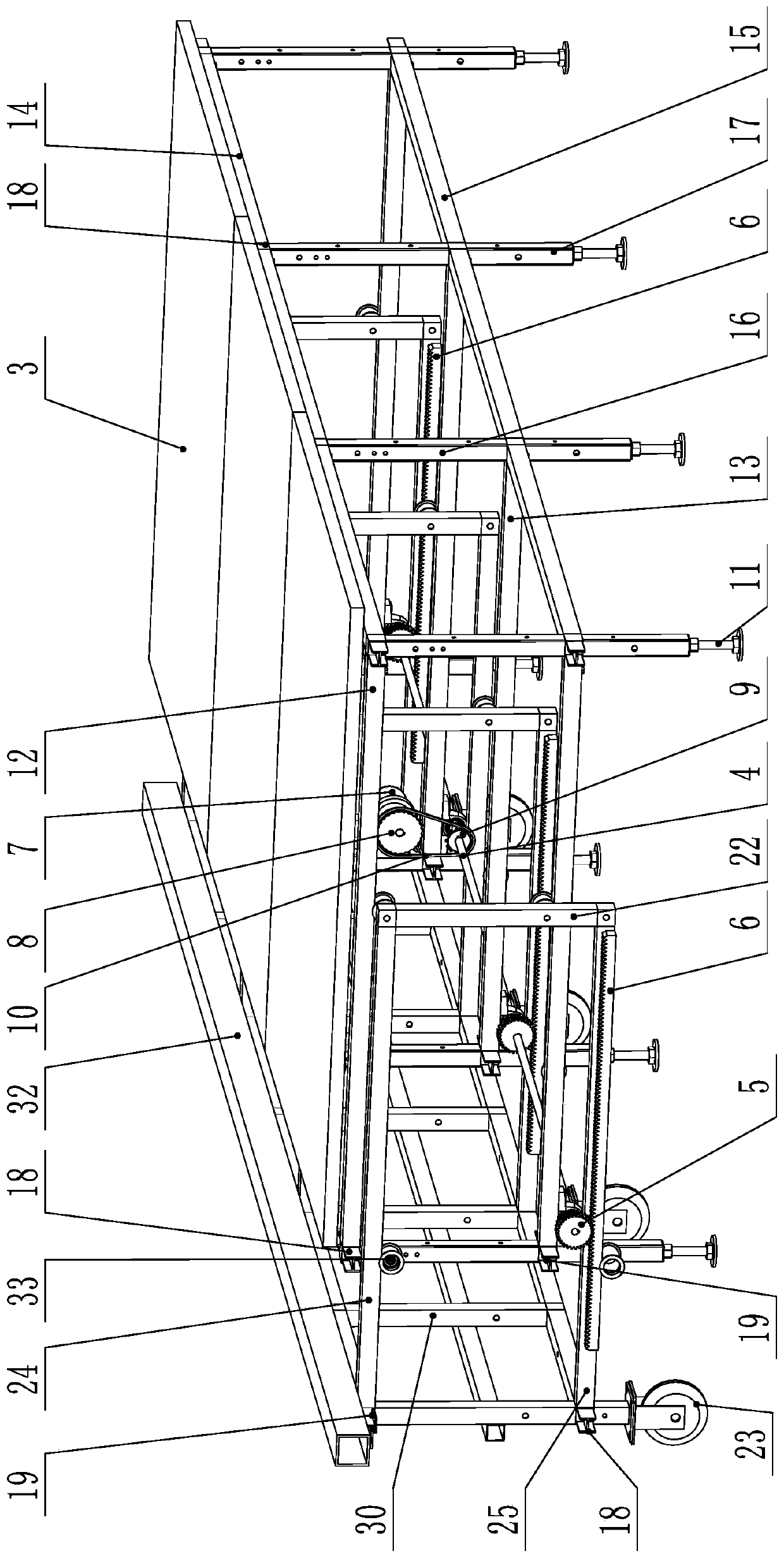
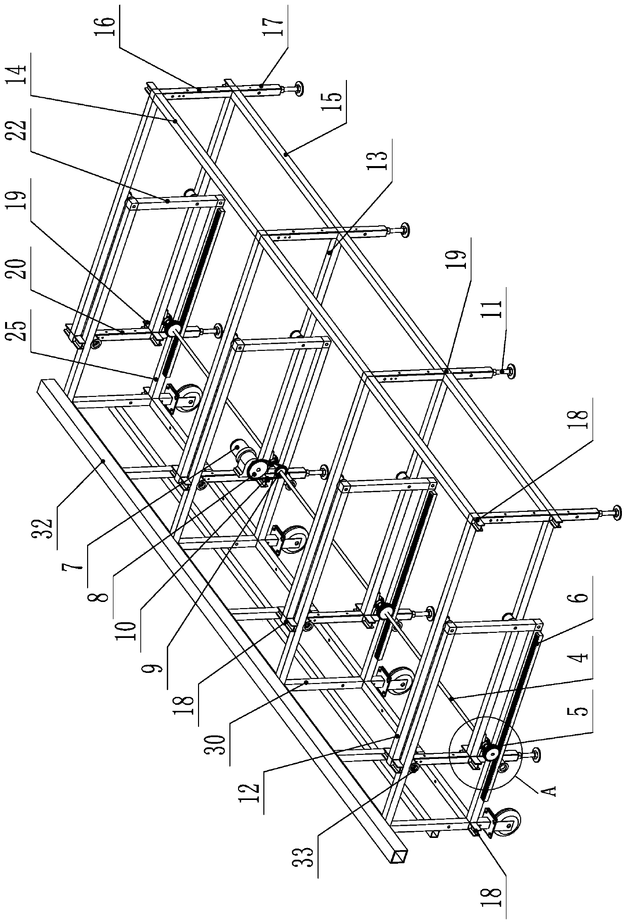
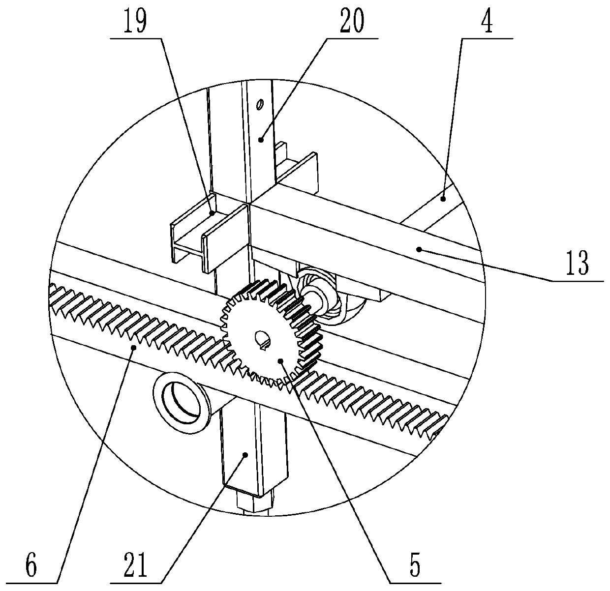
[0036] Example 1: see Figure 1-5 , 10-14:
[0037] A cloth spreading table with adjustable width includes a fixed frame 1 and a movable frame 2. One side of the movable frame 2 extends into the fixed frame 1. The fixed frame 1 and the movable frame 2 are connected by a driving mechanism. The driving mechanism moves along the width direction of the fixed frame 1 to expand outward or contract inward to adjust the width of the spreading table. A cloth table board 3 is provided on the top of the fixed frame 1.
[0038] Further, the driving mechanism includes a transmission shaft 4 which is arranged on the fixed frame 1 and is arranged along the length direction of the fixed frame 1. A plurality of transmission gears 5 are arranged on the transmission shaft 4 at intervals, and each transmission gear 5 They are all engaged with corresponding racks 6 for transmission. The racks 6 are arranged on the movable frame 2 and arranged along the width direction of the movable frame 2, and the t...
Embodiment 2
[0057] Example 2: see Figure 6-14 :
[0058] The difference between this embodiment and the first embodiment lies in the difference in the driving mechanism.
[0059] The driving mechanism described in this embodiment includes a transmission shaft 4 and an auxiliary transmission shaft 39. The transmission shaft 4 and the auxiliary transmission shaft 39 are arranged on the fixed frame 1 at intervals, and the transmission shaft 4 and the auxiliary transmission shaft 39 are arranged along the fixed frame 1 Length direction setting. Specifically, the transmission shaft 4 and the auxiliary transmission shaft 39 are mounted on the bottom plane of the first lower cross beam 13 through bearings and bearing seats. A number of first synchronous pulleys 40 are arranged at intervals on the transmission shaft 4, and second synchronous pulleys 41 corresponding to the positions and numbers of the first synchronous pulleys 40 are arranged on the auxiliary transmission shaft 39. The timing belt...
PUM
 Abstract
Description
Claims
Application Information
 - R&D
- Intellectual Property
- Life Sciences
- Materials
- Tech Scout
- Unparalleled Data Quality
- Higher Quality Content
- 60% Fewer Hallucinations
Browse by: Latest US Patents, China's latest patents, Technical Efficacy Thesaurus, Application Domain, Technology Topic, Popular Technical Reports.
© 2025 PatSnap. All rights reserved.Legal|Privacy policy|Modern Slavery Act Transparency Statement|Sitemap|About US| Contact US: help@patsnap.com


