Lock

A secondary lock and deadbolt technology, applied in the field of locks, can solve the problem that the entire lock cannot operate normally

Active Publication Date: 2019-09-20
GEZE GMBH
View PDF6 Cites 0 Cited by
  • Summary
  • Abstract
  • Description
  • Claims
  • Application Information

AI Technical Summary

Problems solved by technology

Furthermore, in the event of a failure of one of the locking elements, for example one such locking element is jammed, the entire lock cannot function properly

Method used


Image

  • Lock
  • Lock
  • Lock

Examples


Embodiment Construction

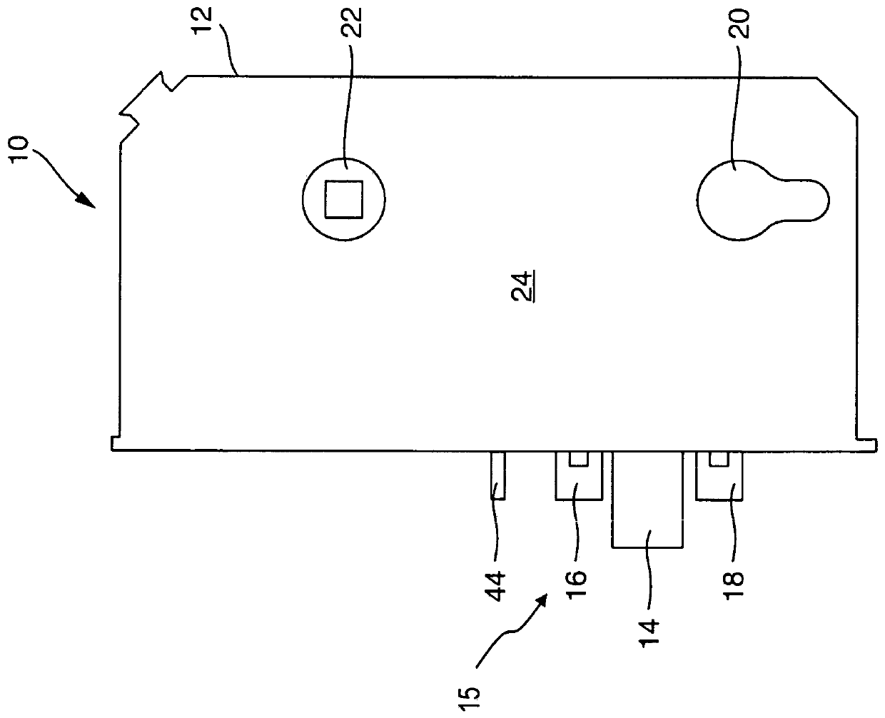
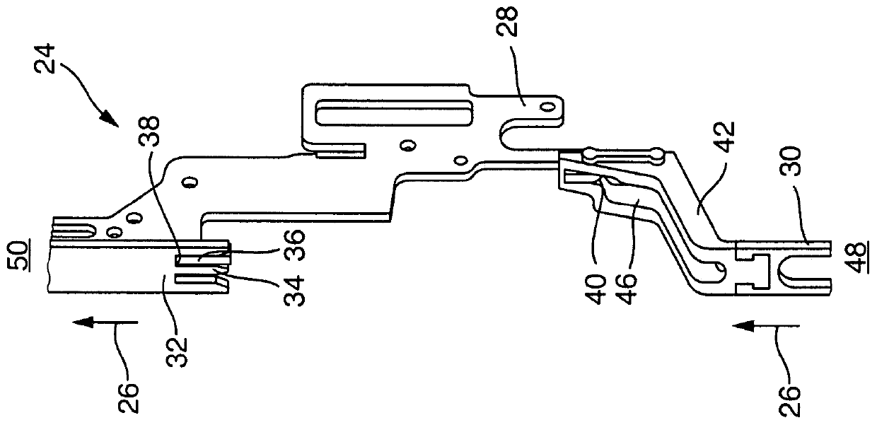
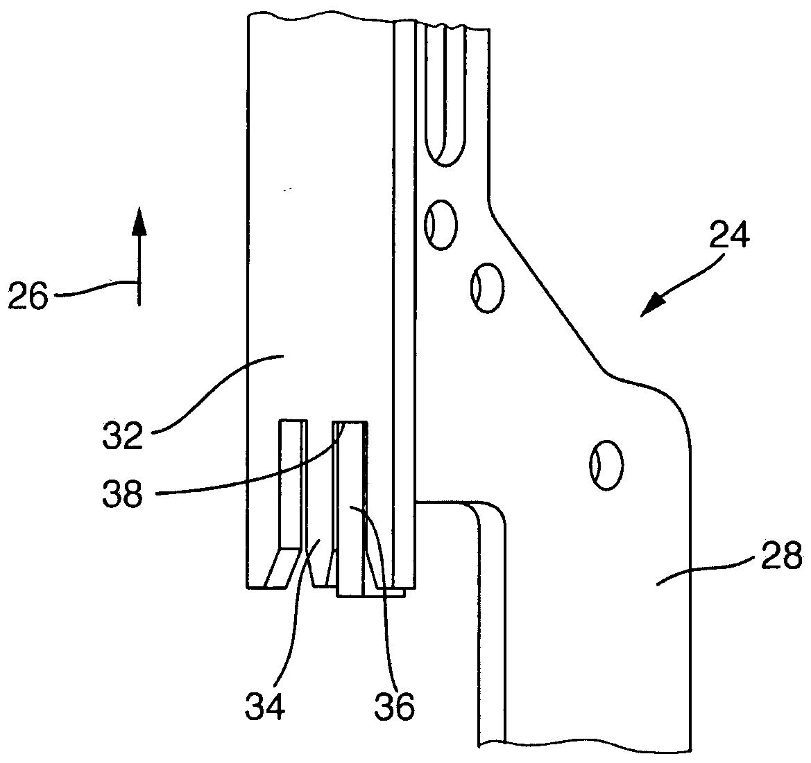
[0032] Figure 1 to 7 A schematic diagram showing an exemplary embodiment of the lock 10 according to the present invention, the lock includes a plurality of locking elements 14, 14A, 48, 50, each of the locking elements can be respectively in the extended locking position and Movement between retracted unlocked positions. In addition, the lock 10 can be provided with a lock cylinder 20 and a button hole (Drückernuss) 22 (see figure 1 with 5 ).

[0033] For example, the lock 10 can be configured as a purely mechanical, self-locking lock and equipped with an emergency function, wherein the lock 10 can be unlocked at any time by operating a button (Drücker) from one side, and can be opened only via the lock cylinder 20 from the other side Locking structure is possible. However, the lock 10 can also be configured, for example, with a separate button hole 22, which can be operated electromagnetically or electromechanically. Therefore, there is a possibility that the button on the l...


PUM


Abstract

The invention relates to a lock comprising a plurality of locking elements, each of said locking elements being respectively movable between an extended locking position and a retracted unlocking position. The locking element includes a main locking element actuated via a lock transmission arranged in the lock box and at least one auxiliary locking element, which is preloaded by elastic force into its extended locking position and can The lock transmission is acted upon via a form-locking connection only in the opening direction in which the auxiliary locking element moves against the direction of the spring force from its extended locking position to its retracted unlocking position.

Description

Technical field [0001] The present invention relates to a lock. The lock includes a plurality of locking elements, and each of the locking elements can move between an extended locking position and a retracted unlocking position. Background technique [0002] In the locks with multiple locking structures known so far, the secondary locking structure is coupled to the lock transmission device provided for operating the main locking structure in this way, and the corresponding locking movement and the corresponding unlocking movement of the lock are directly connected. Passed to the secondary locking element. Therefore, the connection between the secondary locking element and the connecting element assigned to the corresponding secondary locking element is configured to be rigid in the known locks, which results in the remaining locking elements also when operating a certain secondary locking element. Can always exercise together. In addition, when one of the locking elements fai...

Claims


Application Information

Patent Timeline
Patent Type & Authority Patents(China)
IPC IPC(8): E05B63/14E05B65/10E05B15/10
CPCE05B15/108E05B63/146E05B65/1086E05B17/2084E05C9/02E05B15/004
Inventor S·舒恩J·勒克尔
Owner GEZE GMBH
Why Eureka
Try Eureka