
Stereoscopic display device and display method thereof

A technology of a stereoscopic display device and a display method, which is applied in the fields of optics, instruments, nonlinear optics, etc., and can solve problems such as high implementation cost and reduced image resolution

Inactive Publication Date: 2017-11-17
BOE TECH GRP CO LTD
View PDF9 Cites 17 Cited by
  • Summary
  • Abstract
  • Description
  • Claims
  • Application Information

AI Technical Summary

Problems solved by technology

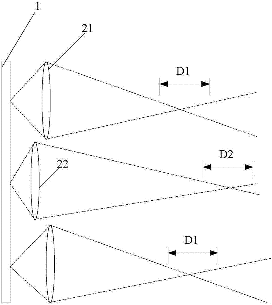
[0003] One implementation in the prior art is to divide the lenses in the lens array into two parts, the first part of the lens has the same object distance, the second part of the lens has the same object distance, and the first part of the lens and the second part of the lens have different object distances , the first part of the lens and the second part of the lens are alternately arranged at different distances in front of the display screen, which will generate two imaging central depth planes, thus increasing the corresponding depth of field range, but for each imaging central depth plane, only half The lens is involved in the imaging process, so the resolution of the image will be reduced and it is necessary to quickly switch between the two lens arrays to obtain a complete image.
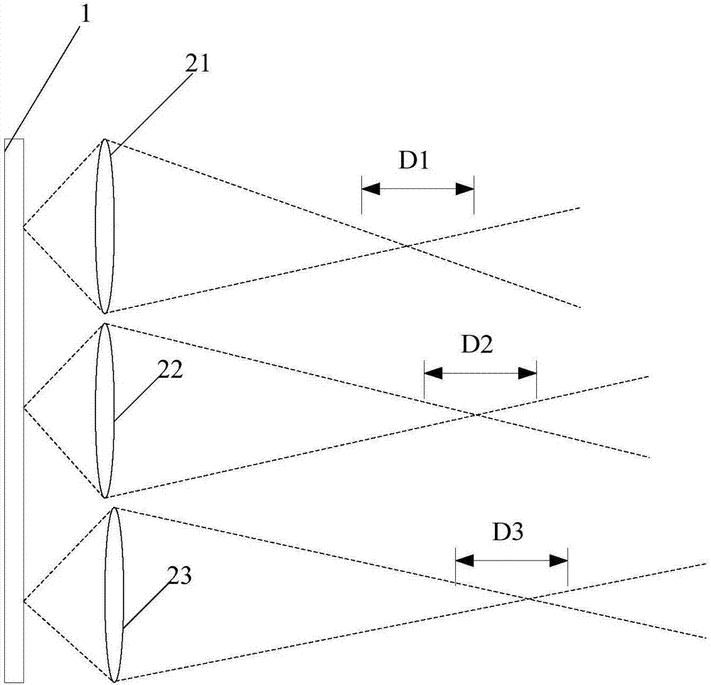
[0004] Another implementation of the existing technology is that the lens array includes multiple lenses with different focal lengths and apertures, so that multiple imaging center depth planes can be generated correspondingly, so that the depth of field range can be increased, but due to the need to process lenses with different apertures and focal lengths lens, so the implementation cost is high

Method used


Image

  • Stereoscopic display device and display method thereof
  • Stereoscopic display device and display method thereof
  • Stereoscopic display device and display method thereof

Examples


Embodiment Construction

[0065] In order to make the technical problems, technical solutions, and advantages to be solved by the embodiments of the present invention clearer, a detailed description will be given below with reference to the drawings and specific embodiments.

[0066] Such as figure 1 As shown, a stereoscopic display device in the prior art divides the lenses in the lens array into two parts. The first part of the lens 21 has the same object distance, the second part of the lens 22 has the same object distance, and the first part of the lens 21 and the second part have the same object distance. The two parts of the lens 22 have different object distances. The first part of the lens 21 and the second part of the lens 22 are alternately arranged at different distances in front of the display screen 1, which will produce two imaging center depth planes D1 and D2, thus increasing the corresponding depth of field However, for each imaging center depth plane, only half of the lenses participate i...


PUM


Abstract

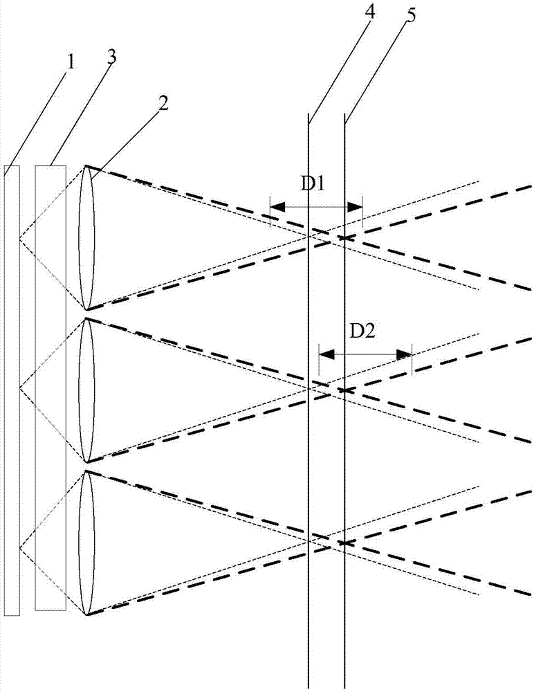
The invention provides a stereoscopic display device and a display method thereof, and belongs to the technical field of display. The stereoscopic display device comprises a display screen and a lens array arranged at the light output side of the display screen. The stereoscopic display device also comprises a spatial light modulator arranged between the display screen and the lens array. The spatial light modulator can be switched between different states; and under different states, light paths of light emitted from the display screen in the spatial light modulator are different. According to the technical scheme, the stereoscopic display device and the display method thereof can provide a plurality of imaging center depth planes.

Description

Technical field [0001] The present invention relates to the field of display technology, in particular to a stereoscopic display device and a display method thereof. Background technique [0002] The object distance and lens focal length of the integrated imaging display system determine the size of the image distance, that is, the position of the depth plane of the integrated imaging center. Since each imaging center depth plane has its corresponding depth of field range, it is possible to change the position of the imaging center depth plane by changing the object distance, that is, the distance between the display device and the reproduction lens array, and generate multiple imaging center depths Plane to increase the system’s stereoscopic display depth. [0003] One implementation in the prior art is to divide the lenses in the lens array into two parts. The first part of the lens has the same object distance, the second part of the lens has the same object distance, and the f...

Claims


Application Information

Patent Timeline
IPC IPC(8): G02B27/22G02F1/1335G02F1/1343G02F1/29
CPCG02B30/27G02F1/133528G02F1/134309G02F1/29
Inventor 马新利
Owner BOE TECH GRP CO LTD
Learn More