Gas absorption cell with flexible structure, adjustable optical path and convenience in disassembly
A gas absorption cell, a technology that is easy to disassemble. It is applied in the direction of color/spectral characteristic measurement, material analysis through optical means, and measurement devices. It can solve the problems of high energy loss, increased cost, and low reflectivity of the lens to reduce costs. , Easy to disassemble, flexible and variable optical path
- Summary
- Abstract
- Description
- Claims
- Application Information
AI Technical Summary
Problems solved by technology
Method used
Image
Examples
Embodiment 1
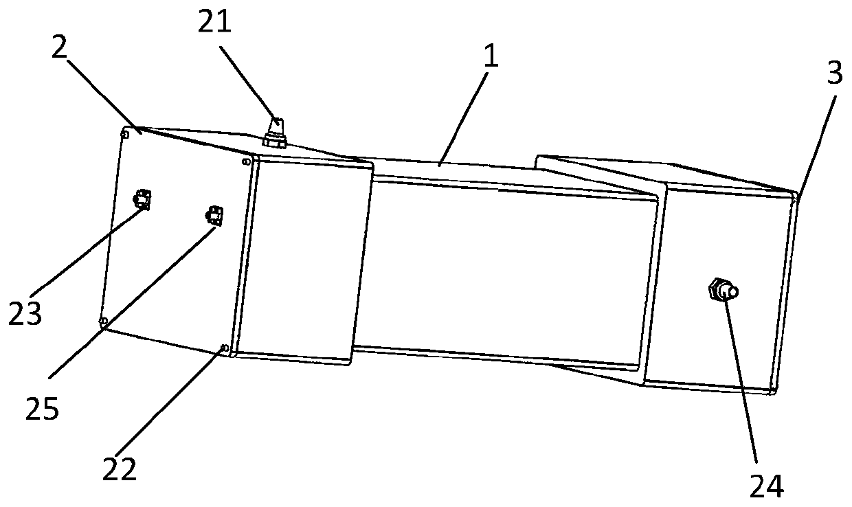
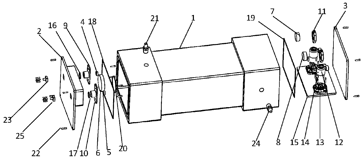
[0047] see figure 2 , image 3 , this embodiment proposes a gas absorption cell with flexible structure, adjustable optical path, and easy disassembly, including a main cavity 1, a front sealing cover 2, a rear sealing cover 3 and a slider 15 integrating a mirror module. An air inlet and an air outlet are provided on the top of the main cavity 1, which can be connected with the air inlet interface 21 and the air outlet interface 24, and a chute for an integrated reflector module is opened at the end for assembling the slider 15; the front end of the front sealing cover 2 A light inlet and a light outlet are provided, and the incident optical fiber connector 23 and the outgoing optical fiber connector 25 are placed respectively, and three placement slots are opened, which can be assembled with the incident lens frame 9, the outgoing lens frame 10, and the first reflector 6. The incident lens frame 9 and the exit lens frame 10 are respectively equipped with an incident lens 4 ...
Embodiment 2
[0049] This embodiment is basically the same as Embodiment 1, and is a more detailed technical description of Embodiment 1.
[0050] see image 3 , The difference between this embodiment and Embodiment 1 is that there are a first sealing gasket 18 and a second sealing gasket 19 between the main cavity 1 and the front sealing cover 2 and the rear sealing cover 3 . Two sealing grooves are formed on both end surfaces of the main cavity 1 for accommodating the first gasket 18 and the second gasket 19 . Both end faces are provided with threaded holes, which can be connected with the front sealing cover 2 and the rear sealing cover 3 by screws 22 .
[0051] see Figure 4 , the front end of the front sealing cover 2 has two square grooves, which can be fixed with the 23 incident optical fiber connector and the 25 outgoing optical fiber connector through the fastening screw 22; Frame 9, outgoing lens frame 10, and first reflector 6 are assembled, and incident lens 4 and outgoing le...
Embodiment 3
[0054] This embodiment provides an optical gas cell structure with specific dimensions.
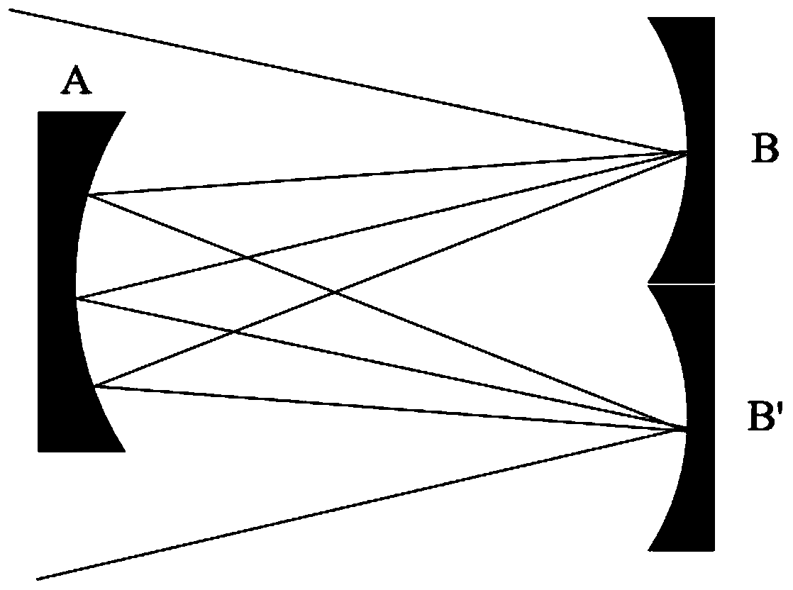
[0055] The radius of curvature of the incident lens and the exit lens of the gas cell is 8.7mm, and the focal length is 17mm; the diameter range of the first concave reflector is 40-100mm, and the radius of curvature is 200mm; the diameter range of the second concave reflector and the third concave reflector Both are 10-30mm, and the radius of curvature is 200mm.
[0056] Adjust the angles of the second concave reflector and the third concave reflector to -6.9° and 6.9° respectively, the number of light reflections is 4 times, and the optical path of the gas pool is 800mm; adjust the second concave reflector and the third concave reflector The angles of the mirrors are -10.2° and 10.2° respectively, the number of light reflections under test is 8 times, and the optical path of the gas pool is 1600mm; the angles of the second concave mirror and the third concave mirror are adjusted to -11....
PUM
 Abstract
Description
Claims
Application Information
 - R&D
- Intellectual Property
- Life Sciences
- Materials
- Tech Scout
- Unparalleled Data Quality
- Higher Quality Content
- 60% Fewer Hallucinations
Browse by: Latest US Patents, China's latest patents, Technical Efficacy Thesaurus, Application Domain, Technology Topic, Popular Technical Reports.
© 2025 PatSnap. All rights reserved.Legal|Privacy policy|Modern Slavery Act Transparency Statement|Sitemap|About US| Contact US: help@patsnap.com


