
Optical path changing device and optical interference system

An optical path change, optical surface technology, applied in the field of optical applications, can solve the problems of high requirement of no tilt and high realization cost, etc.

Inactive Publication Date: 2019-07-09
CHANGCHUN INST OF OPTICS FINE MECHANICS & PHYSICS CHINESE ACAD OF SCI
View PDF5 Cites 0 Cited by
  • Summary
  • Abstract
  • Description
  • Claims
  • Application Information

AI Technical Summary

Problems solved by technology

[0004] The object of the present invention is to provide a device for changing the optical path, which is used in the optical system to change the optical path, which can overcome the high requirements of the existing push-broom method for changing the optical path, which will generate high implementation costs The problem

Method used


Image

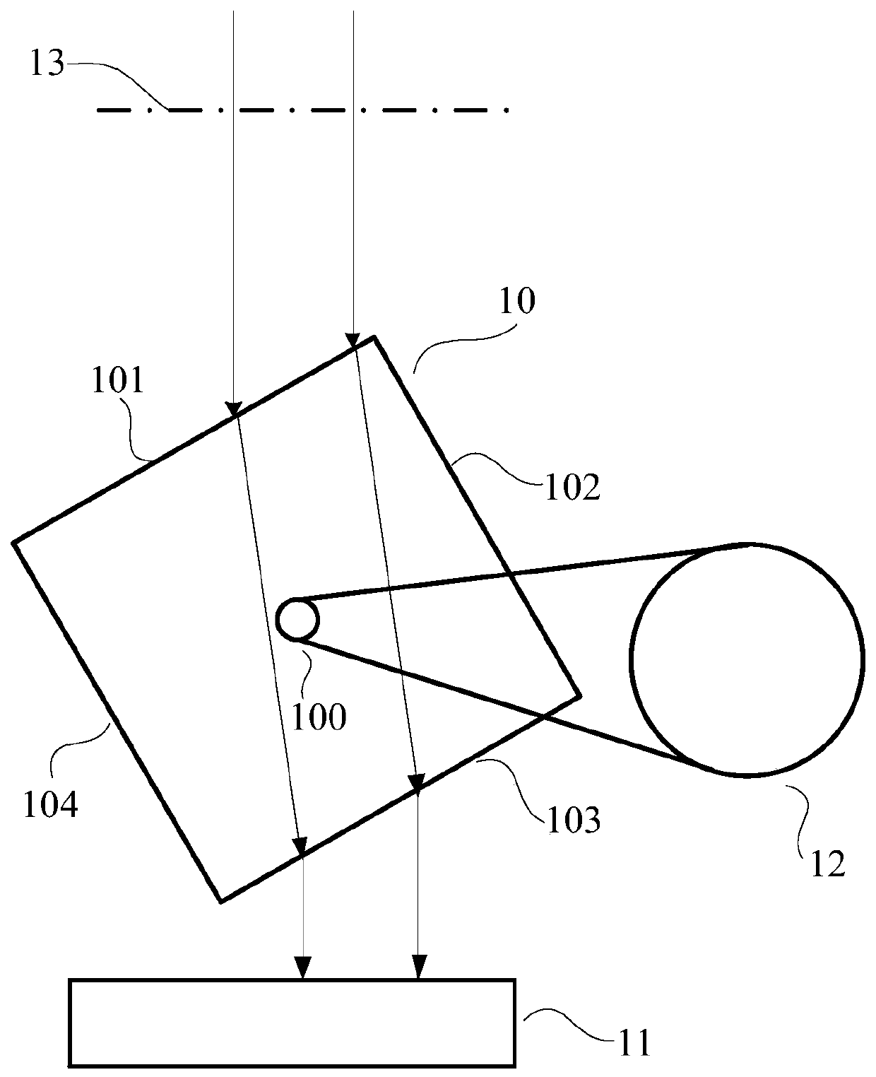
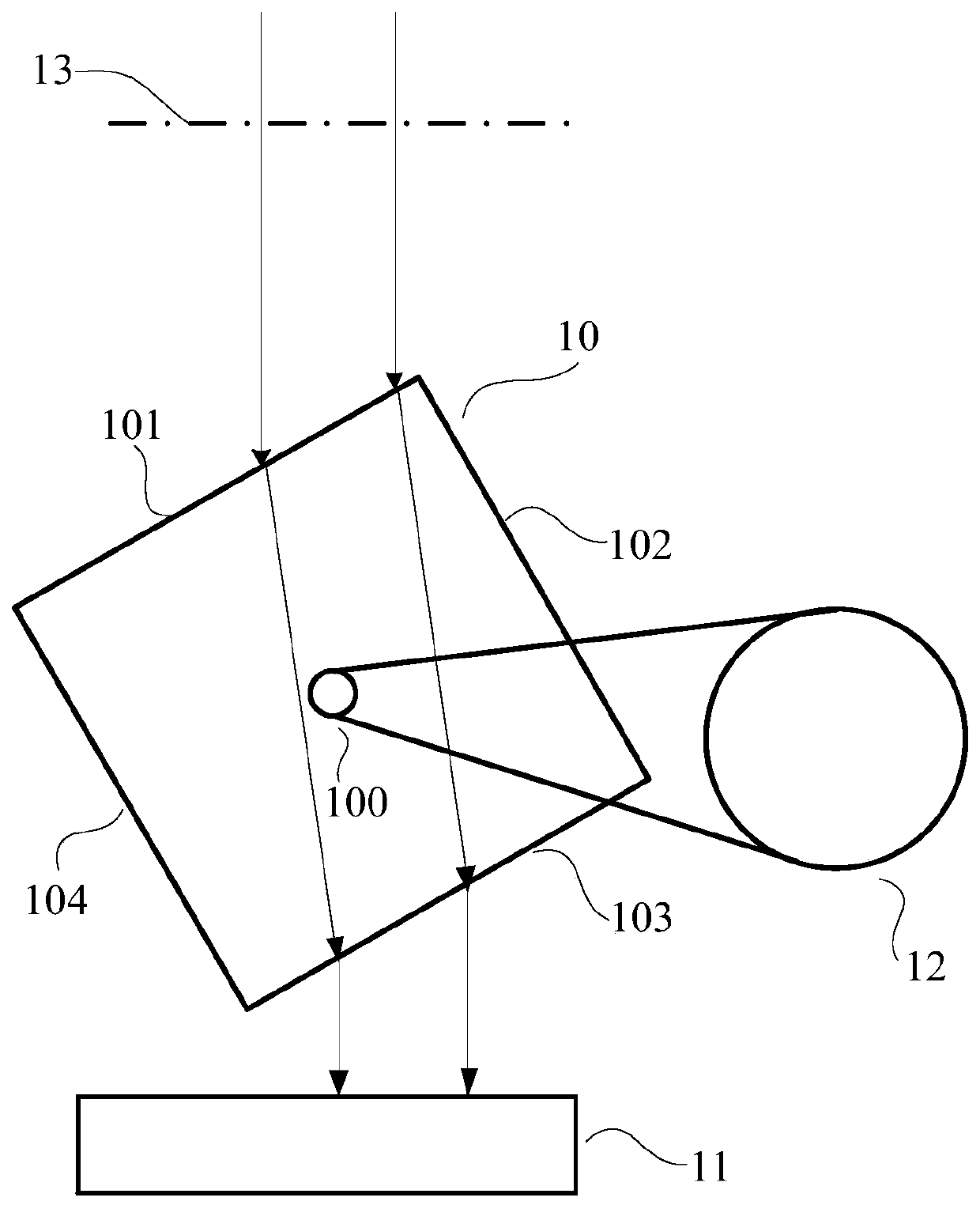
  • Optical path changing device and optical interference system
  • Optical path changing device and optical interference system

Examples


Embodiment Construction

[0020] In order to enable those skilled in the art to better understand the technical solutions in the present invention, the technical solutions in the embodiments of the present invention will be clearly and completely described below in conjunction with the drawings in the embodiments of the present invention. Obviously, the described The embodiments are only some of the embodiments of the present invention, not all of them. Based on the embodiments of the present invention, all other embodiments obtained by persons of ordinary skill in the art without making creative efforts shall fall within the protection scope of the present invention.

[0021] An embodiment of the present invention provides an optical path changing device, which includes a dielectric body and an optical surface. The dielectric body includes a pair of surfaces that are opposite and parallel to each other. Incident light enters the optical path from any one of the pair of surfaces. The dielectric body is...


PUM


Abstract

The invention discloses an optical path changing device and an optical interference system. The optical path changing device comprises a medium body and an optical surface, wherein the medium body comprises coupled surfaces which are face to face and are parallel to each other, incident light enters the medium body from any one of the coupled surfaces, and is transmitted out from the other surfaceof the coupled surfaces, the transmission direction of transmission light is consistent with to the transmission direction of the incident light and the transmission light irradiates the optical surface, the medium body is capable of rotating so that the incident angle of the incident light entering the medium body can be changed, and the optical surface is used for adjusting the transmission direction of the light. In the application of the optical path changing device in the optical system, the problems that an existing push-broom method for changing an optical path has a high requirement for non-tilt, and comparatively high realizing cost is generated are solved.

Description

technical field [0001] The invention relates to the field of optical application technology, in particular to an optical path changing device. The invention also relates to an optical interference system. Background technique [0002] In recent years, with the gradual deepening of the application of optical technology in the field of measurement, applications based on the theory of coherent optics are increasing, such as length measurement, vibration measurement, Fourier transform spectroscopy, etc. Measurement techniques that apply coherent optics theory need to change the optical path difference of the measurement system by changing the optical path of part of the optical path, so that the target information can be obtained according to the change of the optical path difference and through subsequent processing methods. [0003] In the prior art, the method of changing the optical path is mainly the push-broom type. For example, in the time-modulated Fourier transform spe...

Claims


Application Information

Patent Timeline
Patent Type & Authority Applications(China)
IPC IPC(8): G02B26/08G02B27/00
CPCG02B26/0875G02B27/00
Inventor 姚东王檬檬李全超孟令通
Owner CHANGCHUN INST OF OPTICS FINE MECHANICS & PHYSICS CHINESE ACAD OF SCI
Learn More