
Grating compressor and pulse width adjusting method thereof

A grating compressor and grating technology, applied in the laser field, can solve the problems of pulse laser influence, many adjustment links, and large occupied area, and achieve the effect of easy adjustment of pulse width, ensuring stability, and small occupied area

Pending Publication Date: 2020-12-25
杭州奥创光子技术有限公司
View PDF1 Cites 1 Cited by
  • Summary
  • Abstract
  • Description
  • Claims
  • Application Information

AI Technical Summary

Problems solved by technology

[0004] And because the nonlinear effect in the fiber depends on the pulse peak power density, so to reduce the influence of the nonlinear effect in the fiber, the pulse width must be as wide as possible. The wider the pulse width, the more the grating pair in the compressor The longer the distance is, in the current scheme, in order to obtain high-energy ultrashort pulse laser, the grating pair distance of the grating compressor will be very long, reaching several meters
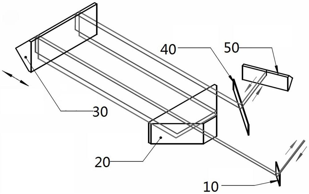
If the optical path is arranged on a plane, multiple reflectors are required to turn back the optical path multiple times, which will occupy a large area and have many adjustment links, which is not conducive to the commercialization of the laser.
[0005] The prior art CN103427316B provides a laser pulse stretching device. In this scheme, the phase delay of the right-angle prism is used to change the laser polarization direction, and the polarized light is combined with multiple mirrors to realize pulse broadening, but this scheme needs to change the polarization of the laser. state, changing the structure of the optical path itself will easily cause the final pulsed laser to be affected; the prior art CN1092286125A provides a highly efficient chirped pulse amplification system, which provides a complex prism combination structure to pass the laser through the chirped multiple times through multiple reflections. Chirped body Bragg gratings achieve multiple compressions, but this method has the defect that the pulse width compression cannot be adjusted, and the complex structure puts forward higher requirements for assembly
[0006] That is to say, if the solution of the prior art is to obtain high-energy ultrashort pulse laser, it is necessary to set a large grating pair distance, so that the grating compressor needs to occupy a large area, which is also not conducive to the commercialization of the grating compressor; However, if the distance between the grating and the distance is sacrificed, a high-energy ultrashort pulse laser with high stability that meets the requirements cannot be obtained. Of course, there are some solutions to improve this problem, but either the stability is not high, or there are problems such as non-adjustable

Method used


Image

  • Grating compressor and pulse width adjusting method thereof
  • Grating compressor and pulse width adjusting method thereof
  • Grating compressor and pulse width adjusting method thereof

Examples


Embodiment Construction

[0022] The following will clearly and completely describe the technical solutions in the embodiments of the present invention with reference to the accompanying drawings in the embodiments of the present invention. Obviously, the described embodiments are only some, not all, embodiments of the present invention. All other embodiments obtained by persons of ordinary skill in the art based on the embodiments of the present invention belong to the protection scope of the present invention.

[0023] Those skilled in the art should understand that in the disclosure of the present invention, the terms "vertical", "transverse", "upper", "lower", "front", "rear", "left", "right", " The orientation or positional relationship indicated by "vertical", "horizontal", "top", "bottom", "inner", "outer", etc. is based on the orientation or positional relationship shown in the drawings, which are only for the convenience of describing the present invention and The above terms should not be con...


PUM


Abstract

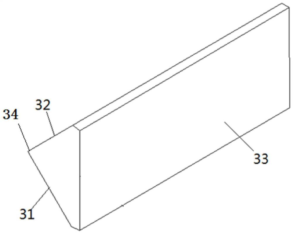
The invention provides a grating compressor, a first prism and a second prism are arranged in a light path between a first grating and a second grating at an interval, and the first prism comprises afirst right-angle surface and a second right-angle surface which are perpendicular to each other and intersect with the intersection line of the right-angle surfaces of the first prism; the first right-angle surface and the second right-angle surface are inclined by 45 degrees relative to the incident direction of the central wavelength light beam; the second prism comprises a first side face anda second side face which are perpendicular to each other and intersect with the intersecting line of the right-angle face of the second prism, the first side face and the second side face are inclinedby 45 degrees relative to the incident direction of the central wavelength light beam, and the reflection area of the first prism and the reflection area of the second prism are oppositely arranged.Every two of the the right-angle surfaces of the first prism, the right-angle surfaces of the second prism, and the light beam. The grating compressor has the advantages that the occupied area is small, the number of optical devices is small, the pulse width is easy to adjust, the pulse width adjusting efficiency is high, and laser adjustment is stable.

Description

technical field [0001] The invention relates to the field of laser technology, in particular to a grating compressor and a pulse width adjustment method thereof. Background technique [0002] Chirped pulse amplification technology (CPA) is widely used in ultrashort pulse fiber lasers. Its principle is to first broaden the ultrashort optical pulse in the time domain, then amplify it to high energy, and finally compress the pulse width back. This technology The peak power of the pulse in the amplifier is effectively reduced, and the limitation of nonlinear effects is avoided, and ultrashort pulses with high peak power can be obtained from this laser system. [0003] At present, laser pulse compression is generally realized by a grating pair compressor. The working principle of the grating pair compressor is: when a positive chirped pulse passes through a parallel grating, it experiences different optical paths for different spectral components, and the optical path experienced...

Claims


Application Information

Patent Timeline
Patent Type & Authority Applications(China)
IPC IPC(8): H01S3/00H01S3/10
CPCH01S3/0057H01S3/10023
Inventor 魏玉凤
Owner 杭州奥创光子技术有限公司
Learn More