Clamp and clamping device

A fixture and clamping technology, applied in the field of inspection, can solve problems such as poor use effect, and achieve the effect of better use effect, huge market application potential and compact mechanism

Active Publication Date: 2017-11-21
广东广铝铝型材有限公司
View PDF8 Cites 1 Cited by
  • Summary
  • Abstract
  • Description
  • Claims
  • Application Information

AI Technical Summary

Problems solved by technology

[0007] The overall effect is poor

Method used


Image

  • Clamp and clamping device
  • Clamp and clamping device
  • Clamp and clamping device

Examples


Embodiment 1

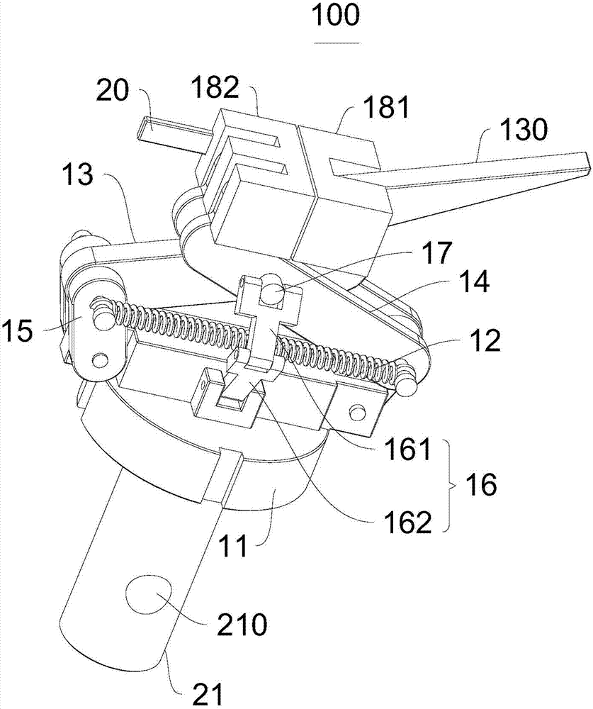
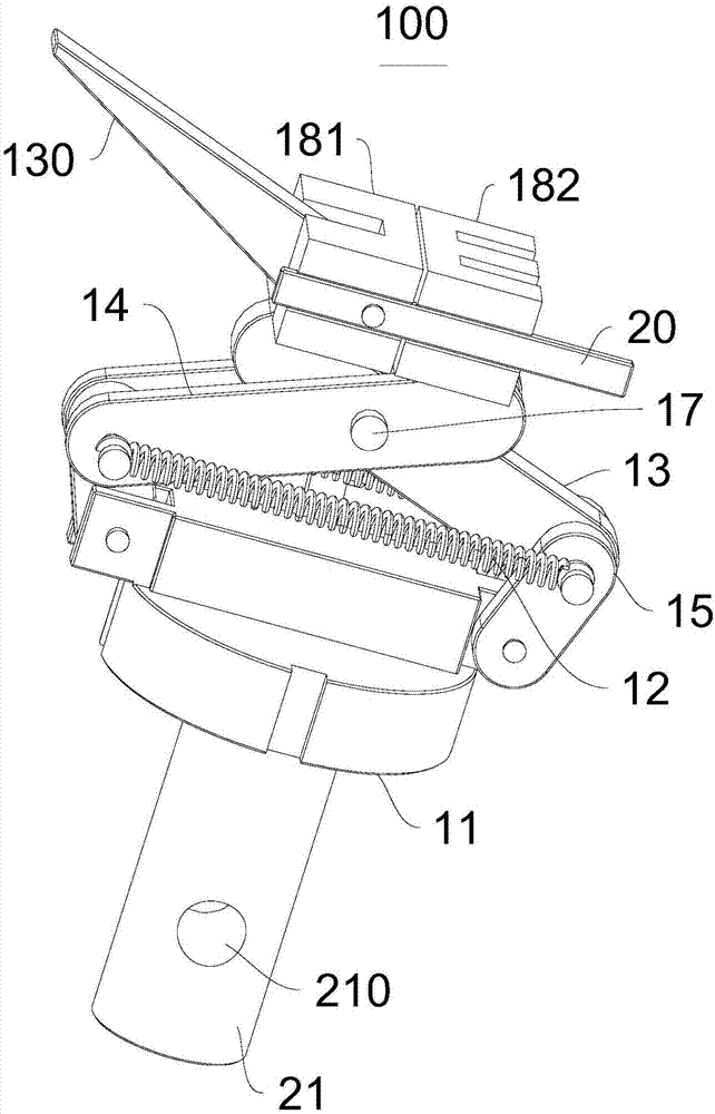
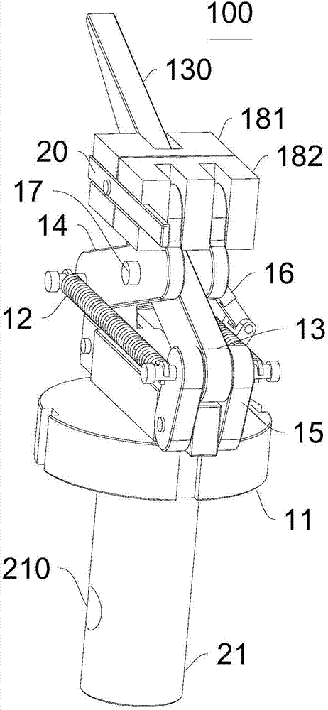
[0039] Please refer to Figure 1-Figure 6 , the present embodiment provides a clamp 100, which includes a clamp body 11, a return member 12 and two clamping parts, the clamping parts have a connecting end and a clamping end, the two clamping parts are crossed and hinged, and the connecting ends can be Rotatingly connected to the clamp body 11 and the connecting ends of the two clamping parts can be close to or away from, the clamping end is located at the end of the clamping part away from the clamping body 11, and the hinge part of the two clamping parts is located at the connecting end and clamping Between the clamping ends, the clamping ends of the two clamping parts cooperate to form a clamping part 180 for clamping objects, and the return member 12 is connected with the clamping parts and makes the two clamping ends move closer to each other.

[0040] Figure 1-Figure 4 Shown are schematic structural views of the jig 100 from different viewing angles.

[0041] Figure ...

Embodiment 2

[0074] Please refer to Figure 7 , this embodiment also provides a clamp 100, the technical solution described in embodiment 1 is also applicable to this embodiment, and the disclosed technical solution in embodiment 1 will not be described again.

[0075] Specifically, the difference between this embodiment and Embodiment 1 is that the clamp 100 further includes a second intermediate piece 19, the second intermediate piece 19 is slidably connected to the clamp body 11, and the connecting end is rotatably connected to the second intermediate piece 19 .

[0076] The second intermediate piece 19 and the clamp body 11 are slidingly connected, and the first connecting end 132 and the second connecting end 142 are rotationally connected with the corresponding second intermediate piece 19, and the clamp 100 is in the clamping state and to be clamped When switching between states, the first connecting end 132 and the second connecting end 142 can realize the effect of the first conn...

Embodiment 3

[0078] This embodiment also provides a clamping device, which includes a frame and the above-mentioned clamp 100, the side of the clamp body 11 away from the clamping component is provided with a fixing member 21 for fixed connection with the frame, the fixing component 21 is provided with a fixing hole 210 .

[0079] The structure of the clamp 100 can refer to Embodiment 1 or 2, and the clamping device has all the functions of the clamp 100 .

[0080] The frame can be a test table or a fixed frame on the wall. When testing is required, the fixing part 21 is installed on the frame through the fixing hole 210 to realize the stability of the entire fixture 100 . It should be noted here that the clamp 100 may also be directly fixed on the frame through the fixing member 21 .

[0081] In this embodiment, the fixture 100 is used to clamp the aluminum profile and perform measurement work on it. Similarly, it can also measure other items.

[0082] In summary, the present invention ...


PUM


Abstract

The invention provides a clamp and a clamping device, and belongs to the technical field of detection. The clamp comprises a clamp body, a restoring piece and two clamping pieces, wherein each clamping piece is provided with a connecting end and a clamping end, the two clamping pieces are crossed and hinged, the connecting ends can be rotationally connected to the clamp body and the connecting ends of the two clamping pieces can be close to or far away from each other, each clamping end is located at one end, away from the clamp body, of each clamping piece, the hinge part of the two clamping pieces is located between the connecting ends and the clamping ends, the clamping ends of the two clamping pieces are matched to form a clamping part for clamping objects, and the restoring part is connected with the clamping pieces and makes the two clamping ends have a moving tendency towards each other. The clamp can clamp the aluminum profile through the two clamping pieces. According to the clamp, the design is reasonable, the clamp can help a user to quickly measure the aluminum profile, the overall using effect is good, the mechanism of the clamp is compact, and the market application potential is huge. The clamping device comprises the clamp and has all the functions of the clamp.

Description

technical field [0001] The invention relates to the technical field of detection, in particular to a clamp and clamping equipment. Background technique [0002] Fixture: a device used to fix the processing object in the process of mechanical manufacturing so that it can occupy the correct position to accept construction or inspection, also known as fixture. [0003] In a broad sense, any process in the process, the device used to install the workpiece quickly, conveniently and safely, can be called a fixture. Such as welding fixtures, inspection fixtures, assembly fixtures, machine tool fixtures, etc. Among them, machine tool fixtures are the most common, often referred to as fixtures. [0004] When processing a workpiece on a machine tool, in order to make the surface of the workpiece meet the technical requirements such as the size, geometric shape, and mutual position accuracy with other surfaces specified in the drawing, the workpiece must be installed (positioned) and...

Claims


Application Information

Patent Timeline
Patent Type & Authority Applications(China)
IPC IPC(8): B25B11/00
CPCB25B11/00
Inventor 康宇苑韦金旺
Owner 广东广铝铝型材有限公司
Why Eureka
Try Eureka