Jigs and clamping equipment
A fixture and clamping technology, applied in the field of inspection, can solve problems such as poor use effect, and achieve the effect of better use effect, compact mechanism and reasonable design
- Summary
- Abstract
- Description
- Claims
- Application Information
AI Technical Summary
Problems solved by technology
Method used
Image
Examples
Embodiment 1
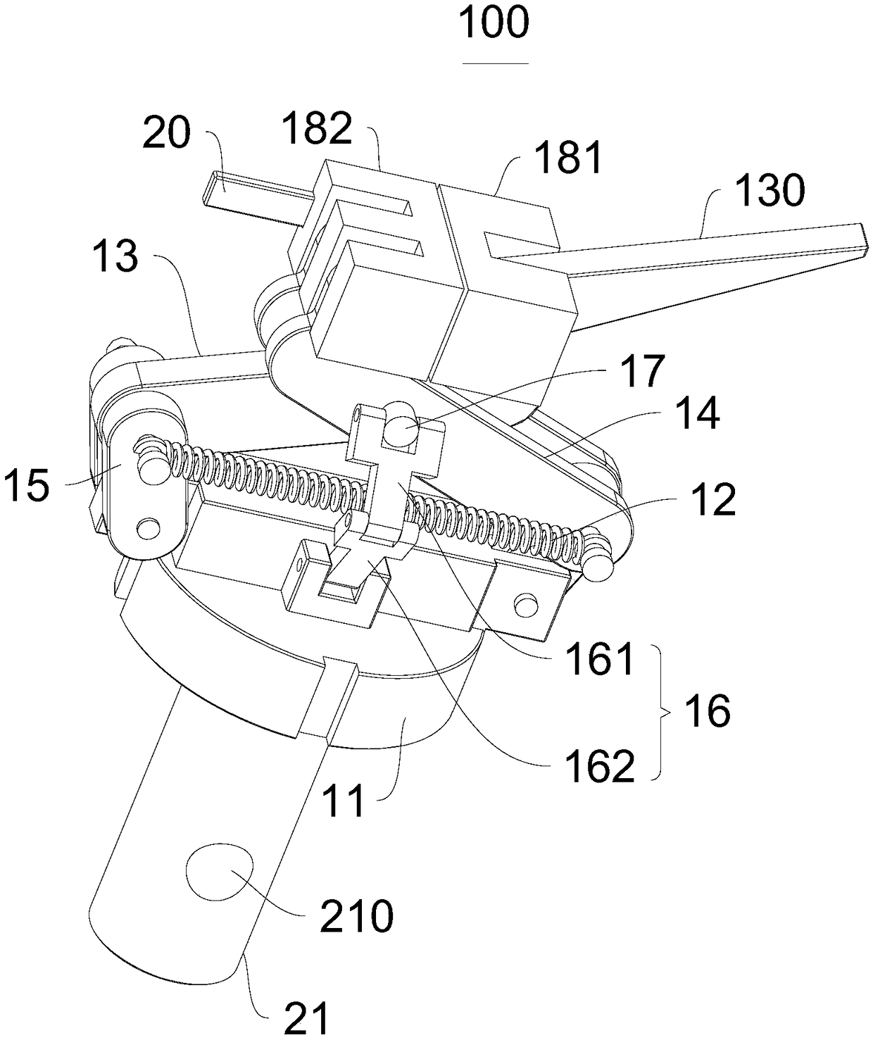
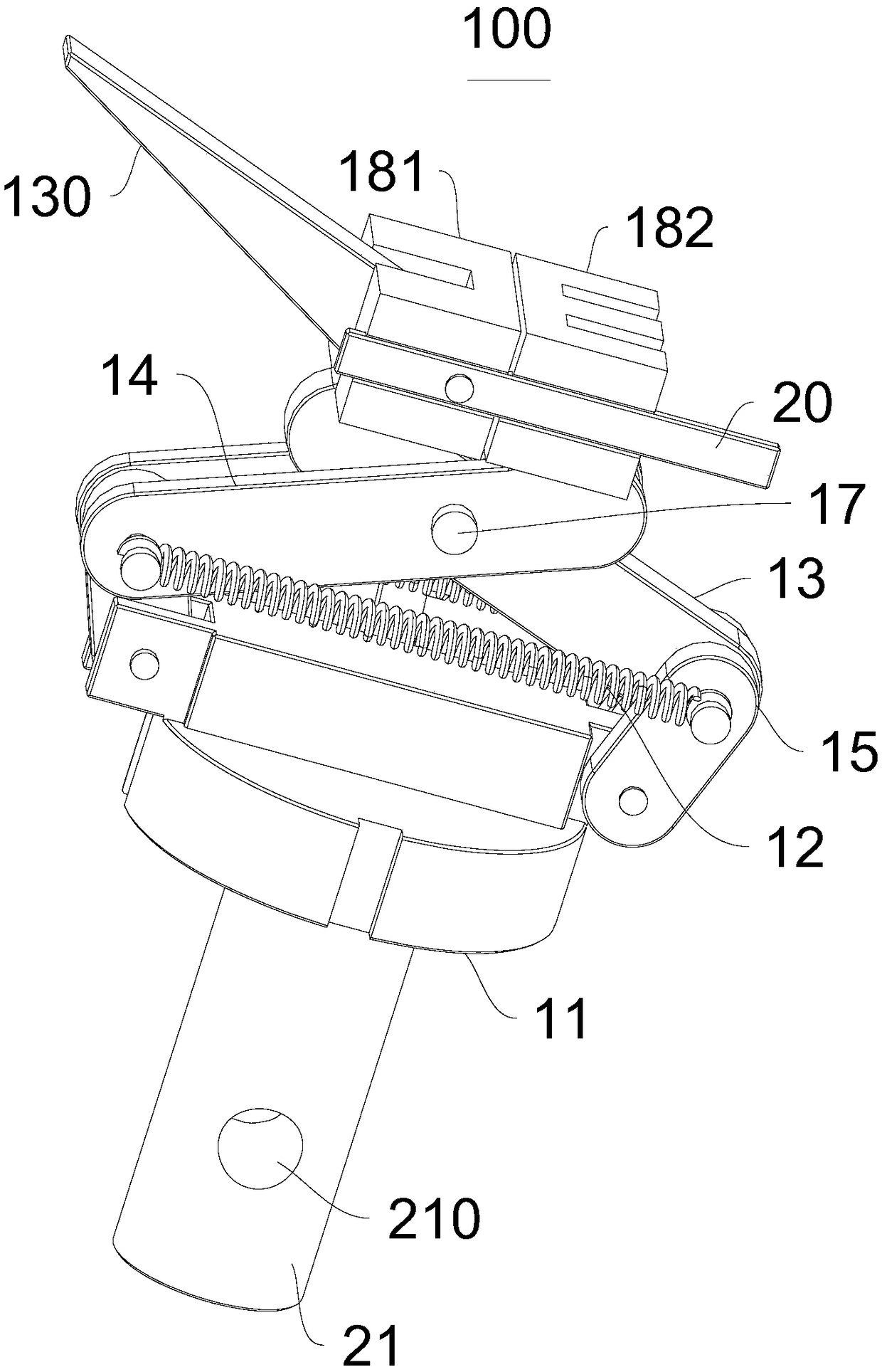
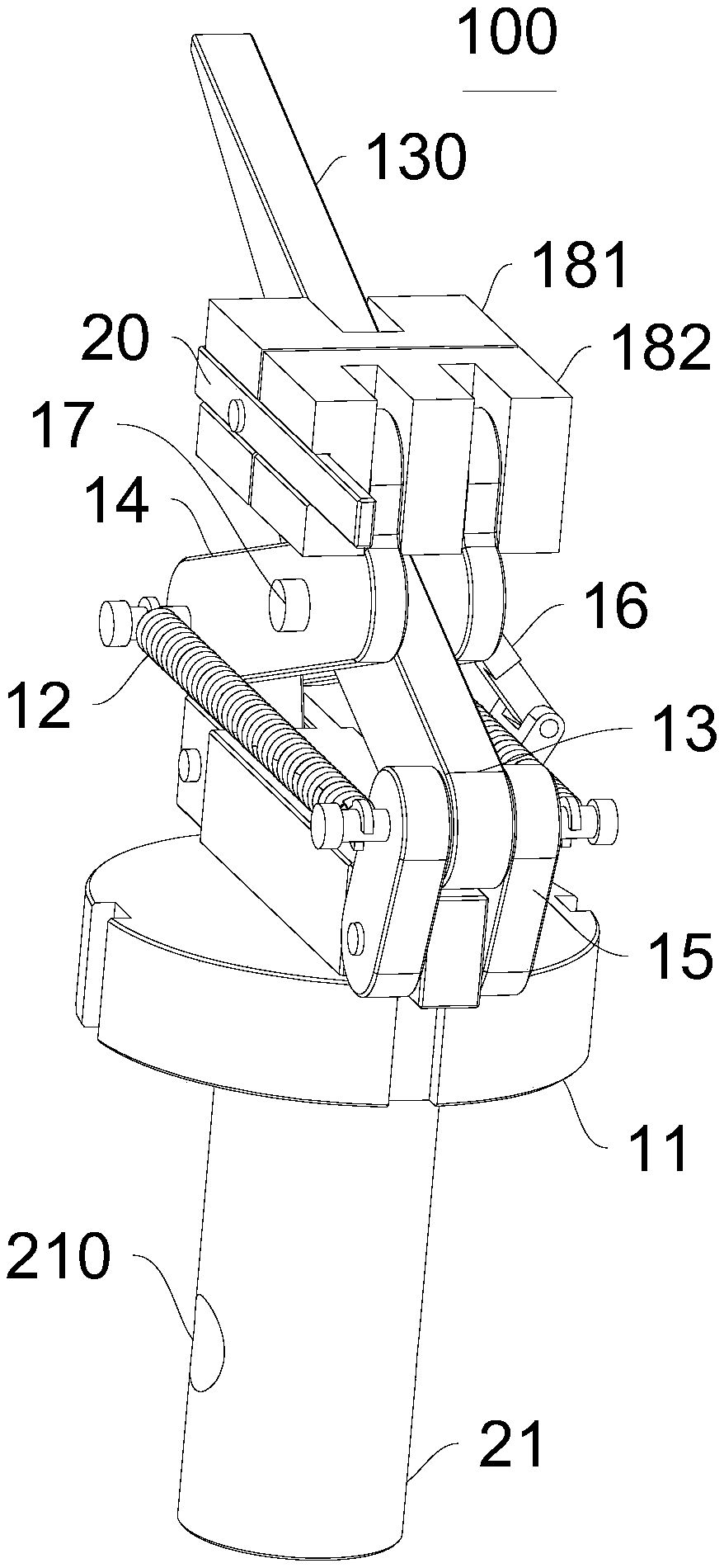
[0039] Please refer to Figure 1-Figure 6 , the present embodiment provides a clamp 100, which includes a clamp body 11, a return member 12 and two clamping parts, the clamping parts have a connecting end and a clamping end, the two clamping parts are crossed and hinged, and the connecting ends can be Rotatingly connected to the clamp body 11 and the connecting ends of the two clamping parts can be close to or away from, the clamping end is located at the end of the clamping part away from the clamping body 11, and the hinge part of the two clamping parts is located at the connecting end and clamping Between the clamping ends, the clamping ends of the two clamping parts cooperate to form a clamping part 180 for clamping objects, and the return member 12 is connected with the clamping parts and makes the two clamping ends move closer to each other.
[0040] Figure 1-Figure 4 Shown are schematic structural views of the jig 100 from different viewing angles.
[0041] Figure ...
Embodiment 2
[0074] Please refer to Figure 7 , this embodiment also provides a clamp 100, the technical solution described in embodiment 1 is also applicable to this embodiment, and the disclosed technical solution in embodiment 1 will not be described again.
[0075] Specifically, the difference between this embodiment and Embodiment 1 is that the clamp 100 further includes a second intermediate piece 19, the second intermediate piece 19 is slidably connected to the clamp body 11, and the connecting end is rotatably connected to the second intermediate piece 19 .
[0076] The second intermediate piece 19 and the clamp body 11 are slidingly connected, and the first connecting end 132 and the second connecting end 142 are rotationally connected with the corresponding second intermediate piece 19, and the clamp 100 is in the clamping state and to be clamped When switching between states, the first connecting end 132 and the second connecting end 142 can realize the effect of the first conn...
Embodiment 3
[0078] This embodiment also provides a clamping device, which includes a frame and the above-mentioned clamp 100, the side of the clamp body 11 away from the clamping component is provided with a fixing member 21 for fixed connection with the frame, the fixing component 21 is provided with a fixing hole 210 .
[0079] The structure of the clamp 100 can refer to Embodiment 1 or 2, and the clamping device has all the functions of the clamp 100 .
[0080] The frame can be a test table or a fixed frame on the wall. When testing is required, the fixing part 21 is installed on the frame through the fixing hole 210 to realize the stability of the entire fixture 100 . It should be noted here that the clamp 100 may also be directly fixed on the frame through the fixing member 21 .
[0081] In this embodiment, the fixture 100 is used to clamp the aluminum profile and perform measurement work on it. Similarly, it can also measure other items.
[0082] In summary, the present invention ...
PUM
 Abstract
Description
Claims
Application Information
 - R&D
- Intellectual Property
- Life Sciences
- Materials
- Tech Scout
- Unparalleled Data Quality
- Higher Quality Content
- 60% Fewer Hallucinations
Browse by: Latest US Patents, China's latest patents, Technical Efficacy Thesaurus, Application Domain, Technology Topic, Popular Technical Reports.
© 2025 PatSnap. All rights reserved.Legal|Privacy policy|Modern Slavery Act Transparency Statement|Sitemap|About US| Contact US: help@patsnap.com


