
Multifunctional field synchronous fertilization device

A fertilization device and a multifunctional technology, which are applied to the field of multifunctional field synchronous fertilization devices, can solve the problems of low fertilization efficiency, consume workers' physical strength, and do not consider soil, etc., achieve efficient ditching and backfilling, improve fertilization efficiency, and high fertilization efficiency Effect

Inactive Publication Date: 2017-11-24
陈钦先
View PDF0 Cites 9 Cited by
  • Summary
  • Abstract
  • Description
  • Claims
  • Application Information

AI Technical Summary

Problems solved by technology

Because the supply of most nutrients is sufficient, otherwise it will cause waste and even cause crop poisoning
this is sometimes overlooked
Second, after the fertilizer is applied to the soil, a series of changes will occur, which will affect the fertilizer effect to varying degrees. If the soil is not considered, it is impossible to talk about the real rational fertilization
[0003] The traditional method of fertilization is to spread fertilizer manually, which not only consumes a lot of physical strength of workers, but also has low fertilization efficiency, and it is easy to cause uneven fertilizer spreading, resulting in too much or too little fertilizer in some areas, which wastes fertilizer; Furrow fertilization can improve the fertilizer efficiency of deep soil. The traditional manual slotting is inefficient and troublesome to operate; the existing fertilization device is to spread fertilizer and water or liquid fertilizer separately, which requires multiple operations, which reduces the operation efficiency and improves the efficiency. mechanical operating cost

Method used


Image

  • Multifunctional field synchronous fertilization device
  • Multifunctional field synchronous fertilization device
  • Multifunctional field synchronous fertilization device

Examples


Embodiment Construction

[0020] The technical solutions in the embodiments of the present invention will be clearly and completely described below with reference to the accompanying drawings in the embodiments of the present invention. Obviously, the described embodiments are only a part of the embodiments of the present invention, but not all of the embodiments. Based on the embodiments of the present invention, all other embodiments obtained by those of ordinary skill in the art without creative efforts shall fall within the protection scope of the present invention.

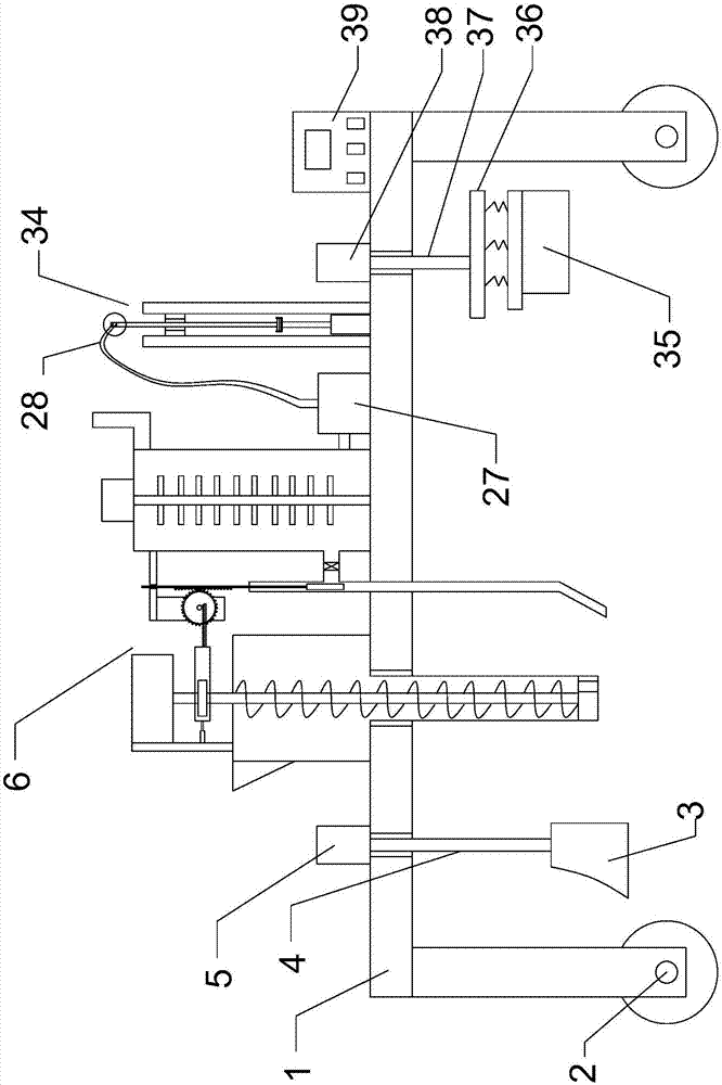
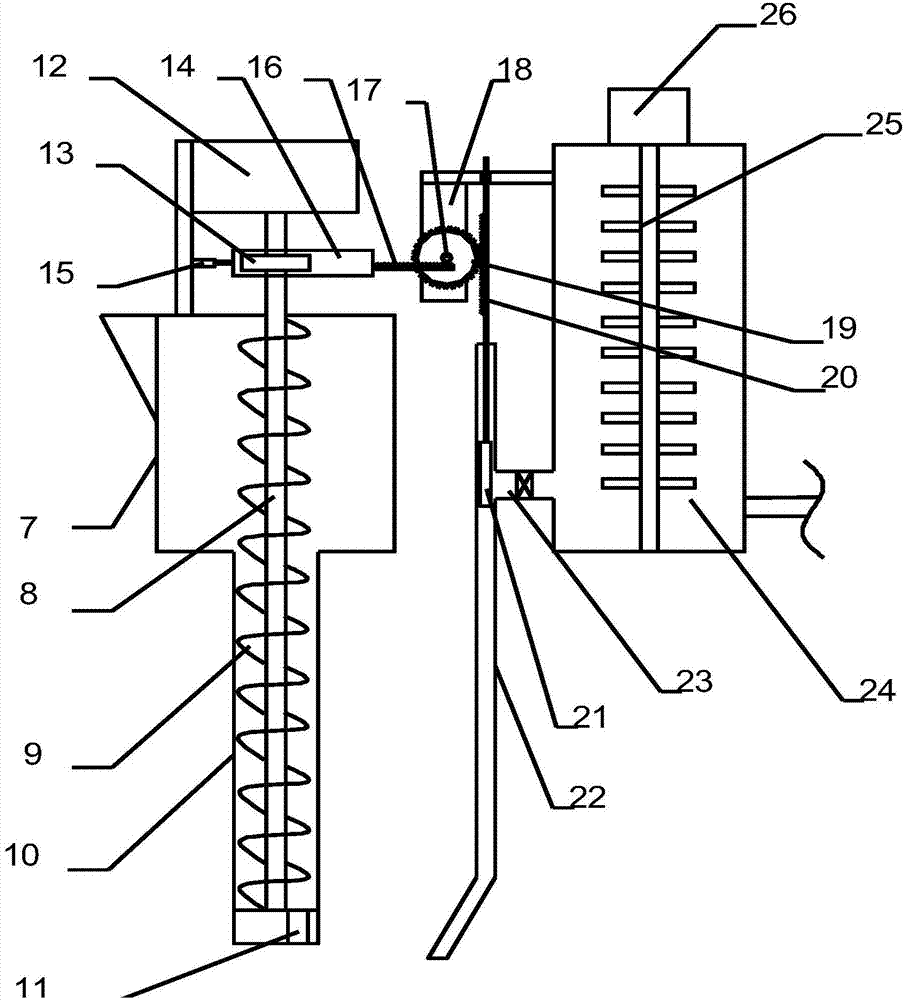
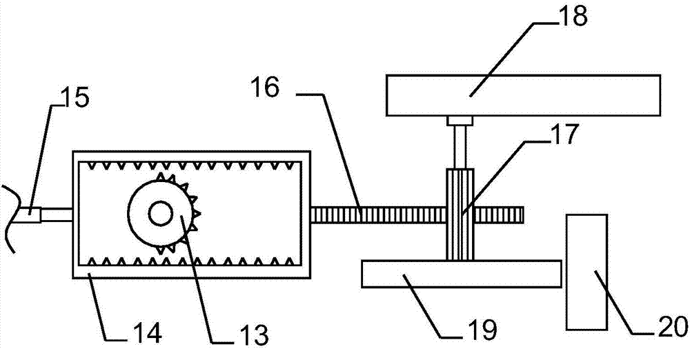
[0021] see Figures 1 to 5 , In the embodiment of the present invention, a multi-functional field synchronous fertilization device includes a vehicle body 1 and a driving wheel 2; the bottom of the vehicle body 1 is provided with a roller 2, and the roller 2 is provided with a driving device to facilitate the movement of the device; the roller 2. There is a ditching plowshare 3 on the right side, the top of the ditching plowshare 3 is...


PUM


Abstract

The invention discloses a multifunctional field synchronous fertilization device, which comprises a vehicle body, wherein the right side of the vehicle body is provided with a ditching plowshare; the vehicle body is provided with a synchronous fertilization and watering device. The multifunctional field synchronous fertilization device is provided with the ditching plowshare with adjustable height and a backfilling plate for carrying out efficient ditching and backfilling on a field, so as to bring convenience to fertilization. The multifunctional field synchronous fertilization device is provided with the synchronous fertilization and watering device, liquid fertilizer or water is synchronously applied to a groove while solid fertilization is carried out, and therefore, fertilization efficiency is high. The multifunctional field synchronous fertilization device is provided with an anti-blockage discharging device controlled by a driving motor, so that a fertilization amount can be accurately controlled, fertilization is guaranteed to be even, and fertilizer is saved. The multifunctional field synchronous fertilization device is provided with a sprinkling device, the position of a shower nozzle is regulated to regulate the sprinkling range of the fertilizer, and fertilization efficiency is improved.

Description

technical field [0001] The invention relates to the field of soil machinery, in particular to a multifunctional field synchronous fertilization device. Background technique [0002] Fertilization must consider the soil, because: First, fertilization is only required when the soil is insufficient for a certain nutrient, and it is not necessary to apply all the necessary elements to the soil. Because the supply of most nutrients is sufficient, otherwise it will cause waste and even cause crop poisoning. This is sometimes overlooked. Second, a series of changes will occur after fertilizer is applied to the soil, which will affect the effect of fertilizer to varying degrees. Without considering the soil, there is no real reasonable fertilizer application. [0003] The traditional method of fertilization is to use manual spreading of fertilizers, which not only consumes a lot of physical strength of workers, but also causes low fertilization efficiency, and it is easy to cause ...

Claims


Application Information

Patent Timeline
Patent Type & Authority Applications(China)
IPC IPC(8): A01C23/00A01C23/04A01C15/18A01C5/06
CPCA01C5/062A01C5/066A01C15/18A01C23/002A01C23/04A01C23/047Y02P60/21
Inventor 陈钦先
Owner 陈钦先
Learn More