[0028] The present invention will be described below based on embodiments. Those of ordinary skill in the art should understand that the drawings provided herein are for illustrative purposes, and the drawings are not necessarily drawn to scale.
[0029] Unless the context clearly requires, the words "including", "including" and other similar words in the entire specification and claims should be interpreted as inclusive rather than exclusive or exhaustive meanings; in other words, "including but not limited to" Meaning.
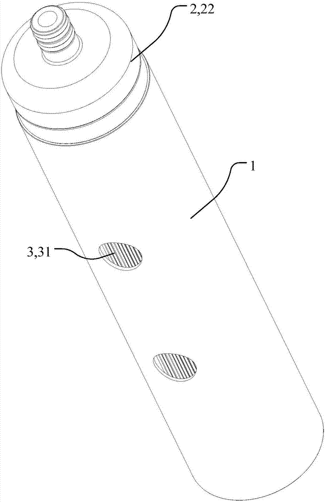
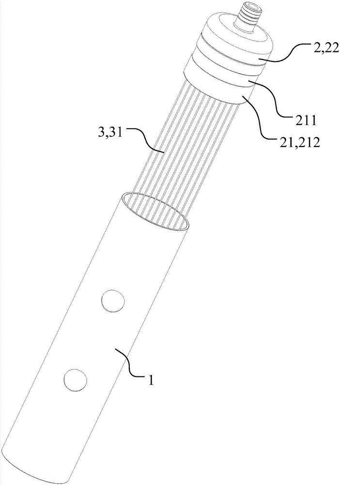
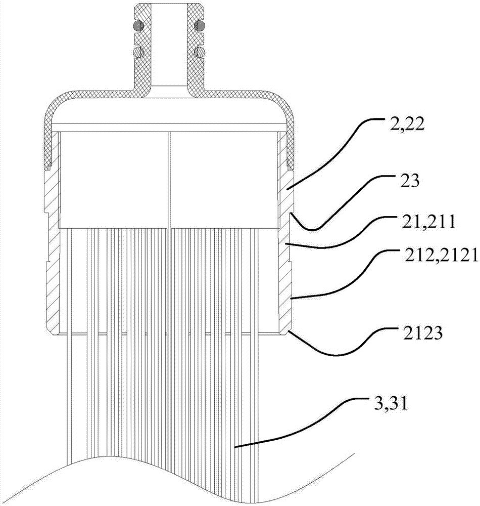
[0030] Such as figure 1 with figure 2 As shown, the detachable filter element provided by the present application includes a cylindrical (usually cylindrical) housing 1, an end 2 and a filter structure 3. The filter structure 3 is used to filter water entering the filter element. The filter structure 3, for example, may be a membrane filament 31, or may have another structure capable of filtering. The filter structure 3 is connected to the terminal 2, for example, can be connected by bonding, plugging, etc. The following takes the membrane filament 31 as an example to introduce the connection structure with the terminal 2, such as Figure 4 As shown, the end 2 has a cylindrical structure that fits the housing 1. One end of the cylindrical structure is open, the other end is closed, and a water outlet is opened on the end surface of the closed end, and the open end of the membrane wire 31 is bonded to form Bundles and integrally adhered in the end head 2, and the membrane filaments 31 are sealedly connected to each other and between the membrane filaments 31 and the inner wall surface of the end head 2 (for example, the sealed connection is realized by glue).
[0031] A filter fit is formed between the housing 1 and the end 2. In normal use, such as figure 1 with Figure 4 As shown, a part of the structure of the end head 2 is inserted into the housing 1, and the end head 2 and the housing 1 jointly define a cavity, so that the membrane filament 31 is accommodated in the cavity. When the membrane filament 31 needs to be rinsed When, such as figure 2 As shown, the end 2 is pulled out of the housing 1, and the membrane filament 31 can be easily taken out.
[0032] Specifically, such as image 3 with Figure 4 As shown, the end 2 includes a first part 21 inserted into the housing 1 and a second part 22 connected to the first part 21. The second part 22 is exposed outside the housing 1, and the first part 21 can form an interference with the housing 1. Cooperate. Of course, it can be understood that it can also be set to a structure in which the housing 1 is inserted into the end 2.
[0033] The structure for forming an interference fit between the first part 21 and the housing 1 can be any structure. For example, in one embodiment, the first part 21 is a cylindrical structure with a uniform outer diameter in the axial direction, and the first part 21 The outer diameter is slightly larger than the inner diameter of the housing 1. Therefore, when the first part 21 is inserted into the housing 1, the first part 21 forms an interference fit with the housing 1. In order to facilitate the installation of the first part 21 into the housing 1, on the first part 21 A guide surface is provided to guide the insertion of the first part 21 into the housing 1.
[0034] In another embodiment, the outer radial direction of the first part 21 gradually decreases away from the second part 22. For example, the outer surface of the first part 21 is a conical surface, and the outer diameter of the first part 21 in a partial area is slightly larger than that of the housing 1. In this way, it is possible to ensure that the first part 21 forms an interference fit with the housing 1, and to facilitate the insertion of the first part 21 into the housing 1.
[0035] In a further preferred embodiment, such as image 3 with Figure 4 As shown, the first part 21 includes a body 211. The body 211 has a cylindrical structure, such as a cylindrical structure with a straight outer diameter in the axial direction. The first part 21 also includes a mating portion 212 provided on the outer wall surface of the body 211. The fitting portion 212 forms an interference fit with the housing 1. The body 211 preferably forms a clearance fit with the housing 1, thereby reducing the surface area of the first part 21 forming an interference fit with the housing 1, reducing the resistance when the first part 21 is inserted into the housing 1, and facilitating the assembly of the filter element.
[0036] The mating part 212 may be, for example, image 3 Shown is an annular protrusion 2121 arranged around the body 211. The radially outer surface of the annular protrusion 2121 forms an interference fit with the inner wall surface of the housing 1. In order to further reduce the surface area of the interference fit, preferably, as Image 6 As shown, the mating portion 212 includes a plurality of protruding structures 2122 arranged at intervals along the circumference of the body 211, and the protruding structures 2122 may be ribs extending along the circumference of the body 211, for example. Of course, the mating portion 212 may also have other structures that can form an interference fit with the housing 1.
[0037] The mating part 212 can be as image 3 As shown in the free end of the body 211, preferably, such as Figure 5 As shown, in the axial direction, a certain distance is set between the mating portion 212 and the free end of the body 211, for example, approximately in the middle of the body 211 in the axial direction. Since the body 211 and the housing 1 are in clearance fit, the body 211 The free end can be easily inserted into the housing 1 first, and play a role in positioning and guiding the subsequent insertion of the mating portion 212.
[0038] Further preferably, such as image 3 with Figure 5 As shown, a guide surface 2123 is provided on the mating portion 212, and the guide surface 2123 is used to guide the insertion of the mating portion 212 into the housing 1, for example, a chamfer between the axially outer side surface and the radially outer side surface of the mating portion 212 , The chamfered surface constitutes the guiding surface.
[0039] Further preferably, the end 2 is also provided with a limiting structure for limiting the position where the end 2 is inserted into the housing 1. The limiting structure may be, for example, a limiting boss provided on the end 2 (not shown in the figure). (Shown), when the end 2 moves to the limit boss and the end surface of the housing 1 close to the end of the end 2, the end 2 is installed in place. For another example, the limiting structure is a stepped structure formed on the side wall of the terminal 2, and the end surface of the housing 1 close to the end of the terminal 2 can abut on the step surface 23 of the stepped structure, thereby limiting the terminal 2 . Preferably, as Figure 4 As shown, the outer diameter of the body 211 is smaller than the outer diameter of the second portion 22, so that the step surface 23 is formed between the body 211 and the second portion 22. The first portion 21 can be inserted into the housing 1, when the step surface 23 abuts When leaning against the end surface of the housing 1, it means that the end 2 is installed in place. On the one hand, it can form a good positioning between the housing 1 and the end 2. On the other hand, the outer part of the second part 22 can be fixed. The diameter is set to be the same as the outer diameter of the housing 1. When the end 2 is connected to the housing 1, the second part 22 is flush with the outer surface of the housing 1 to ensure the flatness of the appearance.
[0040] In addition, the cross-sectional shape of the housing 1 and the end 2 can also be set to be non-circular. In this way, the relative movement of the housing 1 and the end 2 can be guided by the structure of the housing 1 and the end 2 and the relative movement in the circumferential direction can be realized. Position positioning, for example, the cross-section of the housing 1 and the end 2 are triangular, rectangular, elliptical, etc. In addition, the cross-sectional shape of the housing 1 and the end 2 can be set to a non-circular shape. The size of the detachable filter element is reduced in the orientation, thereby facilitating and reasonable use of the installation space, making the structure of the equipment provided with the filter element, such as a water purifier, more compact.