
Turning and milling switching adjusting structure of turning and milling composite machine tool spindle

A composite machine tool, tool spindle technology, applied in manufacturing tools, other manufacturing equipment/tools, metal processing equipment, etc., can solve the problems of low safety factor, waste of time, complex structure, etc., to improve production efficiency, save time, Turn-mill transformation for quick results

Inactive Publication Date: 2017-11-24
宿迁天成锋精机股份有限公司
View PDF1 Cites 0 Cited by
  • Summary
  • Abstract
  • Description
  • Claims
  • Application Information

AI Technical Summary

Problems solved by technology

[0002] Turning and milling machine tools, when in the turning state, the spindle is locked, and in the milling state, the spindle is unlocked, and the motor rotor drives the spindle to rotate. For example, the patent application publication number CN200720082223 discloses a turning and milling composite machine tool spindle turning and milling conversion However, in the process of using the above patents, although the flexible transformation of the tool spindle of the turning and milling machine tool has been realized, the structure is complicated, and the locking operation is performed by hydraulic pressure, the safety factor is not high, the strength is weak, and time is wasted

Method used


Image

  • Turning and milling switching adjusting structure of turning and milling composite machine tool spindle
  • Turning and milling switching adjusting structure of turning and milling composite machine tool spindle
  • Turning and milling switching adjusting structure of turning and milling composite machine tool spindle

Examples


Embodiment Construction

[0015] The following will clearly and completely describe the technical solutions in the embodiments of the present invention with reference to the accompanying drawings in the embodiments of the present invention. Obviously, the described embodiments are only some, not all, embodiments of the present invention. Based on the embodiments of the present invention, all other embodiments obtained by persons of ordinary skill in the art without making creative efforts belong to the protection scope of the present invention.

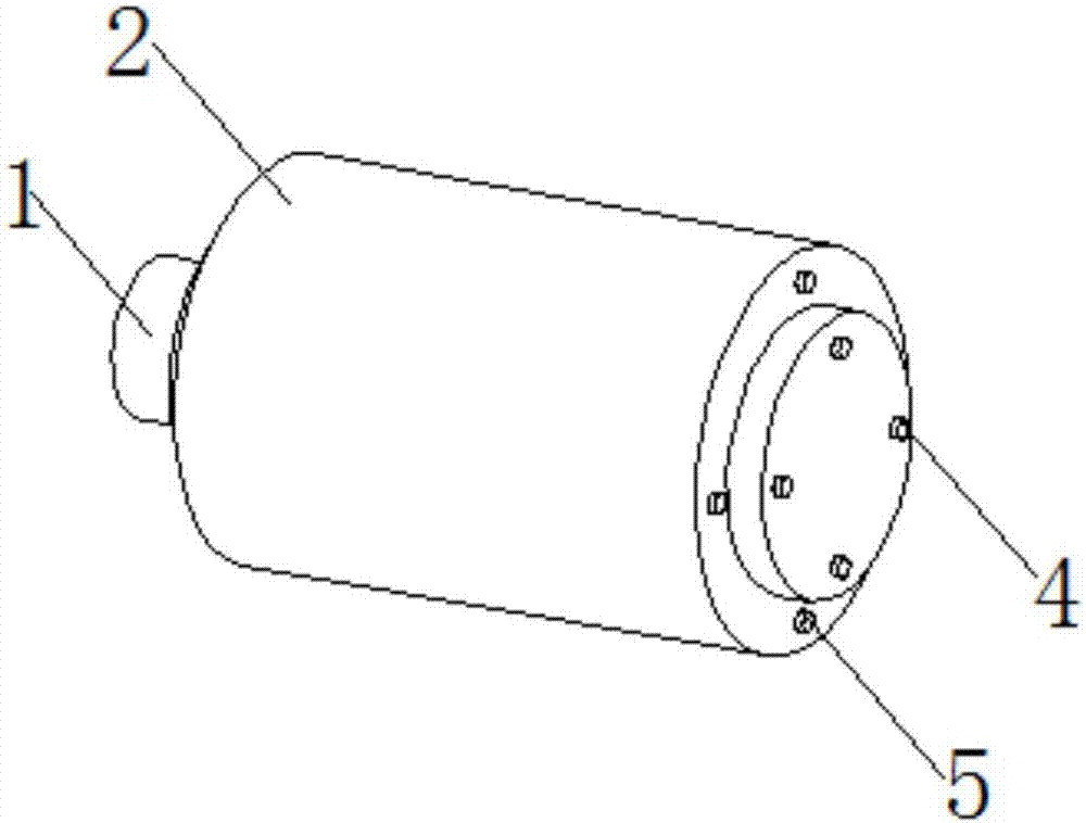
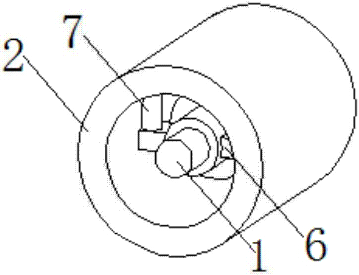
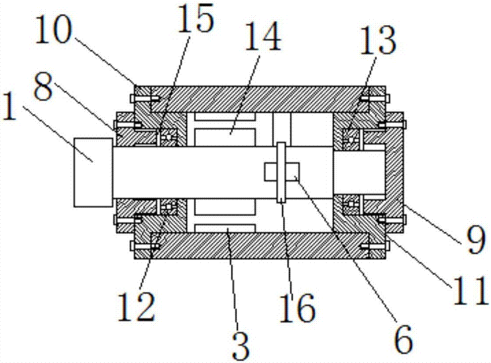
[0016] see Figure 1-3 , the present invention provides a technical solution: an adjustment structure for the turning and milling conversion of the tool spindle of a turning-milling compound machine tool, including a spindle 1 and a casing 2, a strip plate 6 is provided at the right end of the spindle 1, and a positioning pin 16 is provided on the spindle 1 , the strip plate 6 is fixed on the main shaft 1 through the positioning pin 16, the left end of the mai...


PUM


Abstract

The invention discloses an adjustment structure for turning and milling conversion of a tool spindle of a turning-milling compound machine tool, which includes a spindle and a casing. The positioning pin is fixed on the main shaft, the left end of the main shaft is provided with a motor rotor, the inner wall of the housing is provided with a motor stator, the motor stator corresponds to the motor rotor, and the left and right ends of the housing are respectively provided with bearings. Seat 1 and bearing mount 2, the bearing mount 1 and bearing mount 2 are respectively provided with bearing 1 and bearing 2, the structure of the present invention is simple, through the operation of the electric telescopic rod, and then control the telescopic rod in the electric telescopic rod Length, so as to achieve the locking and unlocking of the motor spindle, high strength, safety factor, and at the same time, the turning and milling conversion of the tool spindle can be realized more quickly, saving time and improving the production efficiency of turning and milling.

Description

technical field [0001] The invention relates to the technical field of turning and milling compound machine tool spindle conversion technology, in particular to an adjustment structure for turning and milling compound machine tool spindle turning and milling conversion. Background technique [0002] Turning and milling machine tools, when in the turning state, the spindle is locked, and in the milling state, the spindle is unlocked, and the motor rotor drives the spindle to rotate. For example, the patent application publication number CN200720082223 discloses a turning and milling composite machine tool spindle turning and milling conversion However, in the process of using the above patents, although the flexible transformation of the tool spindle of the turning and milling machine tool has been realized, the structure is complicated, and the locking operation is performed by hydraulic pressure, the safety factor is not high, the strength is weak, and time is wasted. [00...

Claims


Application Information

Patent Timeline
Patent Type & Authority Applications(China)
IPC IPC(8): B23Q5/20B23P23/02
CPCB23Q5/20B23P23/02
Inventor 陆黎琴
Owner 宿迁天成锋精机股份有限公司
Learn More