Biaxial fatigue test clamp

A biaxial fatigue test and fixture technology, applied in the direction of applying stable tension/pressure to test the strength of materials, measuring devices, instruments, etc., can solve the problems of high cost, increase the complexity of the test system, and poor versatility, and achieve The structure is simple, the structure is clear, and the effect of avoiding synchronization problems

Pending Publication Date: 2017-11-24
CRRC CHANGCHUN RAILWAY VEHICLES CO LTD
View PDF0 Cites 10 Cited by
  • Summary
  • Abstract
  • Description
  • Claims
  • Application Information

AI Technical Summary

Problems solved by technology

[0003] Although there are test systems dedicated to biaxial or multiaxial fatigue testing, these test equipment are often expensive and not very versatile
On these test equipment, loads in different directions need to be synchronized by an auxiliary system, which further increases the complexity of the test system

Method used


Image

  • Biaxial fatigue test clamp
  • Biaxial fatigue test clamp
  • Biaxial fatigue test clamp

Examples


Embodiment Construction

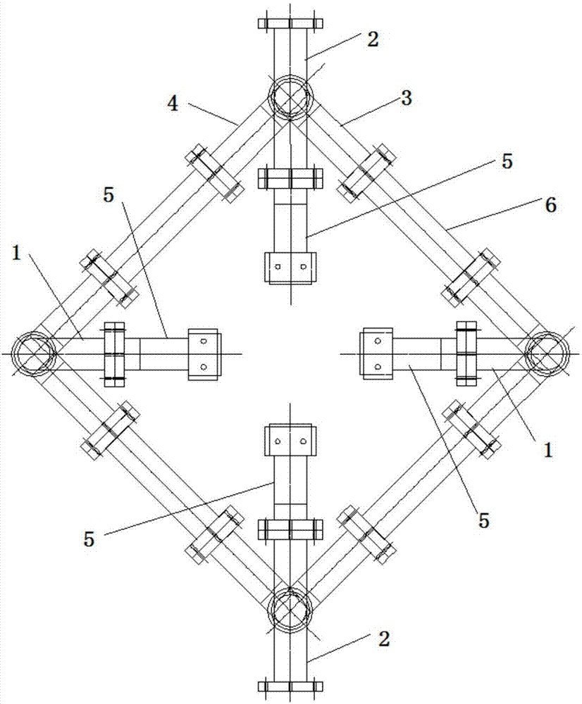
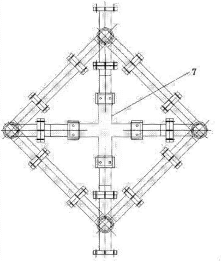
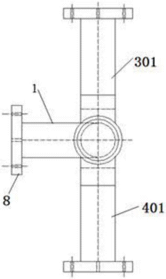
[0023] refer to Figure 1-Figure 2 , the present invention consists of two pivoting arms 3, 4 movably connected to a T-shaped bracket 1 or a cross-shaped bracket 2 to form a T-shaped clamp joint and a cross-shaped clamp joint, and two T-shaped clamp joints and two cross-shaped clamp joints The rotating arms are connected end to end to form a movable quadrilateral frame. The cross-shaped clamp joints are located at the upper and lower ends, and the T-shaped clamp joints are located at the left and right ends. The four clamp joints are respectively connected to a clamp chuck 5, and the other end of the cross-shaped clamp joint is connected to the single shaft. In the fatigue testing machine, sample 7 is connected to four clamps 2 respectively. An extension rod 6 is connected between the connecting arms on each frame of the quadrilateral frame to suit the size of different samples.

[0024] refer to image 3 , Figure 4 , the T-shaped fixture joint is composed of a T-shaped br...


PUM


Abstract

A biaxial fatigue test fixture is characterized in that: two rotating arms are movably connected to two wings of a T-shaped or cross-shaped bracket to form a T-shaped fixture joint and a cross-shaped fixture joint, and the two T-shaped fixture joints The movable quadrilateral frame is formed by connecting the rotating arms of the two cross-shaped fixture joints end to end. One rotating arm of the cross-shaped fixture joint is respectively connected with a clamp chuck, and the other rotating arm of the cross-shaped fixture joint is connected with a uniaxial fatigue testing machine. The invention can utilize the traditional uniaxial fatigue testing machine to realize the biaxial tension and compression fatigue test. The physical structure of the fixture determines the strict consistency of the loading frequency in the x and y directions, avoiding the synchronization problem that occurs in the biaxial fatigue testing machine. The principle is simple, the structure is clear, and it is convenient to use. The extension rod can be easily replaced according to the size of the sample.

Description

technical field [0001] The invention relates to a biaxial fatigue test auxiliary system related to the test field of fatigue performance S-N curve of materials and connection structures, crack growth test in fracture mechanics, etc., and in particular relates to a double fatigue test fixture. Background technique [0002] At present, when studying the fatigue performance of materials or connection structures such as welded joints and riveted joints, test data are generally obtained through uniaxial fatigue tests and crack growth tests. However, in practical applications, the stress state of materials or connected structures is sometimes not uniaxial. In conventional methods, various strength criteria are used to equivalent or convert multiaxial stress to uniaxial stress for research. This approach has significant limitations. [0003] Although there are test systems dedicated to biaxial or multiaxial fatigue tests, these test equipment are often expensive and not universal...

Claims


Application Information

Patent Timeline
Patent Type & Authority Applications(China)
IPC IPC(8): G01N3/04G01N3/08
CPCG01N3/04G01N3/08G01N2203/0073
Inventor 马梦林陈刚张向海
Owner CRRC CHANGCHUN RAILWAY VEHICLES CO LTD
Why Eureka
Try Eureka