
Indoor flyable device for detecting air

A flying device and air chamber technology, which is used in measuring devices, aircraft, unmanned aircraft, etc., can solve the problem that air detection tools cannot detect all corners, etc., and achieve the effect of healthy living space and more living space.

Inactive Publication Date: 2017-11-24
王金锁
View PDF3 Cites 0 Cited by
  • Summary
  • Abstract
  • Description
  • Claims
  • Application Information

AI Technical Summary

Problems solved by technology

[0003] In order to overcome the problem that the air detection tool cannot detect all corners, the present invention provides a new detection tool, which can not only detect air, but also detect air in all directions

Method used


Image

  • Indoor flyable device for detecting air

Examples


Embodiment Construction

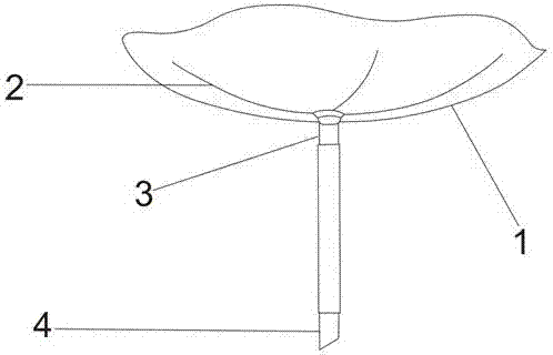
[0009] figure 1 Among them, a flying device for detecting air indoors, which mainly includes a rotary wing (1), an air detector (2), a display rod (3) and a fixed rod (4), which is characterized in that the fixed rod (4) is connected to the display Stick (3), showing that the stick (3) is connected to the rotor (1), and there is an air detector (2) on the rotor (1).

[0010] When in use, separate the rotor (1) from the display stick (3), the rotor (1) rotates in the air, the air detector (2) detects every corner the rotor (1) flies over, and returns to the display stick (3) , the display stick (3) can display the air quality, which improves people's living standards and brings convenience to people.


PUM


Abstract

The invention discloses an indoor flyable device for detecting air. The indoor flyable device mainly comprises a rotating wing, an air detector, a display rod and a fixing rod; the indoor flyable device is characterized in that the fixing rod is connected with the display rod; the display rod is connected with the rotating wing; the air detector is arranged on the rotating wing. In a use process, the air detector can automatically detect air after the rotating wing flies in air. When the rotating wing is connected with the display rod, a detecting result can be displayed. Great convenience is brought to people.

Description

technical field [0001] The invention relates to a testing tool, in particular to a flying device for testing an air chamber. Background technique [0002] At present, with the improvement of people's life, people's quality of life has also improved, and the requirements for air are also higher. People will use many tools to test air quality, but many tools for testing air quality have limitations and cannot Detect every corner of the room, causing confusion to people. Contents of the invention [0003] In order to overcome the problem that the air detection tool cannot detect all corners, the present invention provides a new detection tool, which can not only detect air, but also detect air in all directions. [0004] The technical solution adopted by the present invention to solve the technical problem is: a flying device in the air detection chamber, which mainly includes a fixed rod, a display rod, an air detector and a rotating wing, and is characterized in that the f...

Claims


Application Information

Patent Timeline
IPC IPC(8): G01N33/00B64C27/06
CPCG01N33/0004B64C27/06B64U10/10
Inventor 王金锁
Owner 王金锁
Learn More