Method for calculating time-varying mesh stiffness of bevel gear pair

A technology of time-varying meshing stiffness and helical gear pairs, applied in the field of mechanical dynamics, can solve the problems of not considering nonlinear contact, correcting matrix stiffness and prolonging meshing effects, etc., to improve calculation accuracy, improve calculation accuracy, and improve analytical models Effect

Inactive Publication Date: 2017-11-24
NORTHEASTERN UNIV
View PDF3 Cites 11 Cited by
  • Summary
  • Abstract
  • Description
  • Claims
  • Application Information

AI Technical Summary

Problems solved by technology
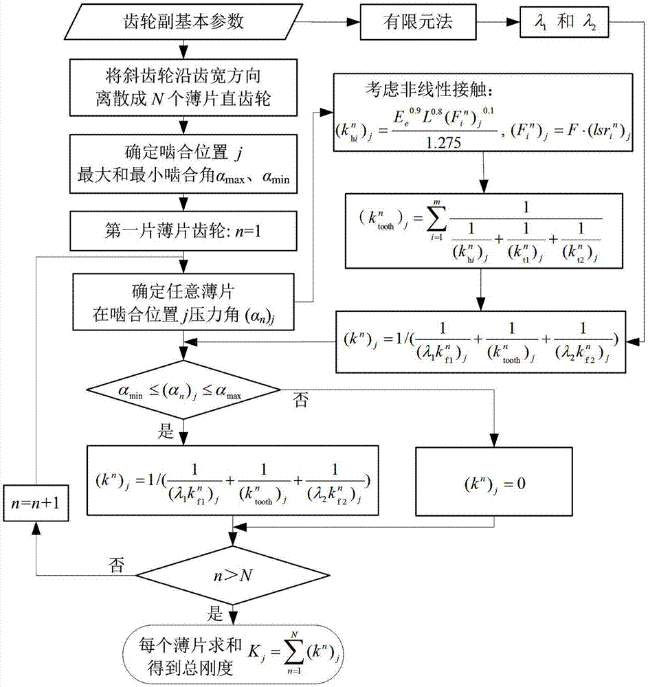
[0011] In order to solve the above problems in the prior art, the present invention provides a calculation method for the time-varying meshing stiffness of helical gear pairs, which is used to solve the limitations of the existing analytical method for calculating the time-varying meshing stiffness of helical gear pairs. Nonlinear contact, modified matrix stiffness, and extended mesh effects

Method used


Image

  • Method for calculating time-varying mesh stiffness of bevel gear pair
  • Method for calculating time-varying mesh stiffness of bevel gear pair
  • Method for calculating time-varying mesh stiffness of bevel gear pair

Examples


Embodiment 1

[0153] In this embodiment, the basic parameters of the helical gear pair are shown in Table 1:

[0154] Table 1 Basic parameters of helical gear pair

[0155]

[0156] Specifically, the helix angles are 12°, 16°, 20°, and 24°. When the entire tooth is engaged, the tooth width L is 60mm, R is 12.738>5, and E e It is 230.769GPa.

[0157] In this example, Figure 4 When the helix angle is 12° and the coincidence degree is 3.0614, the time-varying meshing stiffness diagram of the helical gear obtained by using analytical method, finite element method, ISO6336 or literature 1; Figure 5 When the helix angle is 16° and the coincidence degree is 3.4472, the time-varying meshing stiffness diagram of the helical gear obtained by using analytical method, finite element method, ISO6336 or literature 1; Image 6 When the helix angle is 20° and the coincidence degree is 3.8124, the time-varying meshing stiffness diagram of the helical gear obtained by using analytical method, finite ...

Embodiment 2

[0161] In this embodiment, the basic parameters of the helical gear pair are the same as those in Embodiment 1.

[0162] In this embodiment, the time-varying meshing stiffness fluctuation is measured by the parameter η, and its expression is as follows:

[0163]

[0164] In the formula, ΔK represents the difference between the maximum value and the minimum value of the time-varying meshing stiffness within a meshing period, and K mean Indicates the average stiffness of a meshing cycle, the unit of the two is the same, and the parameter η is just a dimensionless proportional value, which is used to measure the fluctuation of meshing stiffness.

[0165] Specifically, when the helix angle exceeds 30°, the calculation accuracy of the "slicing idea" will be affected. Therefore, in this embodiment, the helix angles are selected as 3°, 5°, 8°, 10°, 13°, 15°, 18°, 20°, 23°, 25°, 28°, 30°, L=60mm.

[0166] In this example, Figure 8 Indicates the relationship between the helix angl...

Embodiment 3

[0169] In this embodiment, the basic parameters of the helical gear pair are the same as those in the first embodiment except that the tooth width is different from that in the first embodiment.

[0170] In this embodiment, the tooth width L is taken to be 10 mm, 15 mm, 20 mm, and 25 mm, respectively.

[0171] In this example, Figure 10 It represents the time-varying meshing stiffness diagram of the helical gear pair when the tooth width is 10mm and 15mm, Figure 11 It is the time-varying mesh stiffness diagram of the helical gear pair when the tooth width is 20mm and 25mm. Wherein, for the working condition of L=10mm, there are single-tooth zone and double-tooth zone, and the single-tooth zone (the ratio of single-tooth zone is only 2.05% of one cycle) is not marked in the figure.

[0172] from Figure 10 with Figure 11 It can be seen that the time-varying meshing stiffness increases with the increase of tooth width, and when the tooth width increases from 10mm to 25mm,...


PUM


Abstract

The invention belongs to the technical field of mechanical dynamics, and particularly relates to a method for calculating time-varying mesh stiffness of a bevel gear pair. The method includes: S1, acquiring basic parameters of the bevel gear pair; S2, separating a bevel gear pair model into N independent and uniform laminar straight gears along a tooth width direction; S3, determining whether the N laminar straight gears participate in meshing or not at the meshing position j; S4, calculating the time-varying mesh stiffness for every laminar straight gear; S5, summing the time-varying mesh stiffness of all the laminar straight gears to obtain the time-varying mesh stiffness of the bevel gear pair. The method for calculating the time-varying mesh stiffness of the bevel gear pair has the advantages that nonlinear contact is taken into consideration, influences of base body stiffness and extended meshing are corrected, an analyzing model is improved, and calculating precision is improved.

Description

technical field [0001] The invention belongs to the technical field of mechanical dynamics, and in particular relates to a calculation method for time-varying meshing stiffness of a helical gear pair. Background technique [0002] Gear transmission can be described as the most widely used form of transmission in the field of mechanical transmission. This wide application is not only due to its own advantages such as precise transmission, high efficiency, reliable operation, and long life, but also benefits from the fact that gear transmission has a relatively complete set of International standards and the development of gear transmission technology have reached a certain level. [0003] It is precisely because gear transmission is indispensable in the field of machinery that attracts more and more domestic and foreign scholars to devote themselves to the research of gear transmission and to promote the development of gear technology. [0004] With the development and progr...

Claims


Application Information

Patent Timeline
Patent Type & Authority Applications(China)
IPC IPC(8): G06F17/50
CPCG06F30/17G06F30/23
Inventor 马辉孙衍宁冯盟蛟闻邦椿张学良
Owner NORTHEASTERN UNIV
Why Eureka
Try Eureka