
Die cutting device

A die-cutting and rolling knife technology, applied in the fields of printing and packaging, can solve the problems of reduced production efficiency and increased production costs, and achieve the effect of easy operation and adjustment

Active Publication Date: 2017-11-28
瑞安市振华印刷机械加工有限公司
View PDF5 Cites 0 Cited by
  • Summary
  • Abstract
  • Description
  • Claims
  • Application Information

AI Technical Summary

Problems solved by technology

For different cutting requirements, it is necessary to replace the rollers to achieve different incision lengths. Therefore, it is necessary to design several sets of rollers according to the needs of the product, which will increase the production cost, and the replacement of the rollers will also reduce the production efficiency.

Method used


Image

  • Die cutting device
  • Die cutting device
  • Die cutting device

Examples


Embodiment Construction

[0024] The present invention will be described in further detail below by means of specific embodiments:

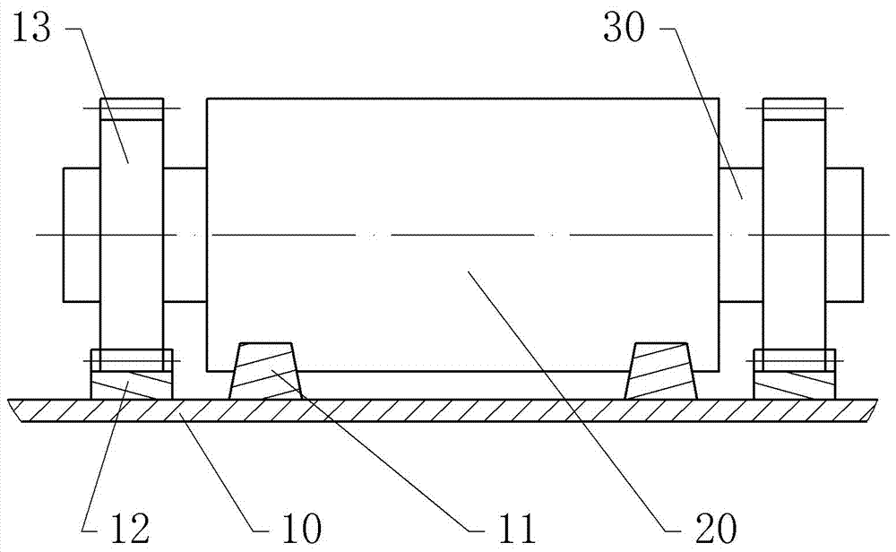
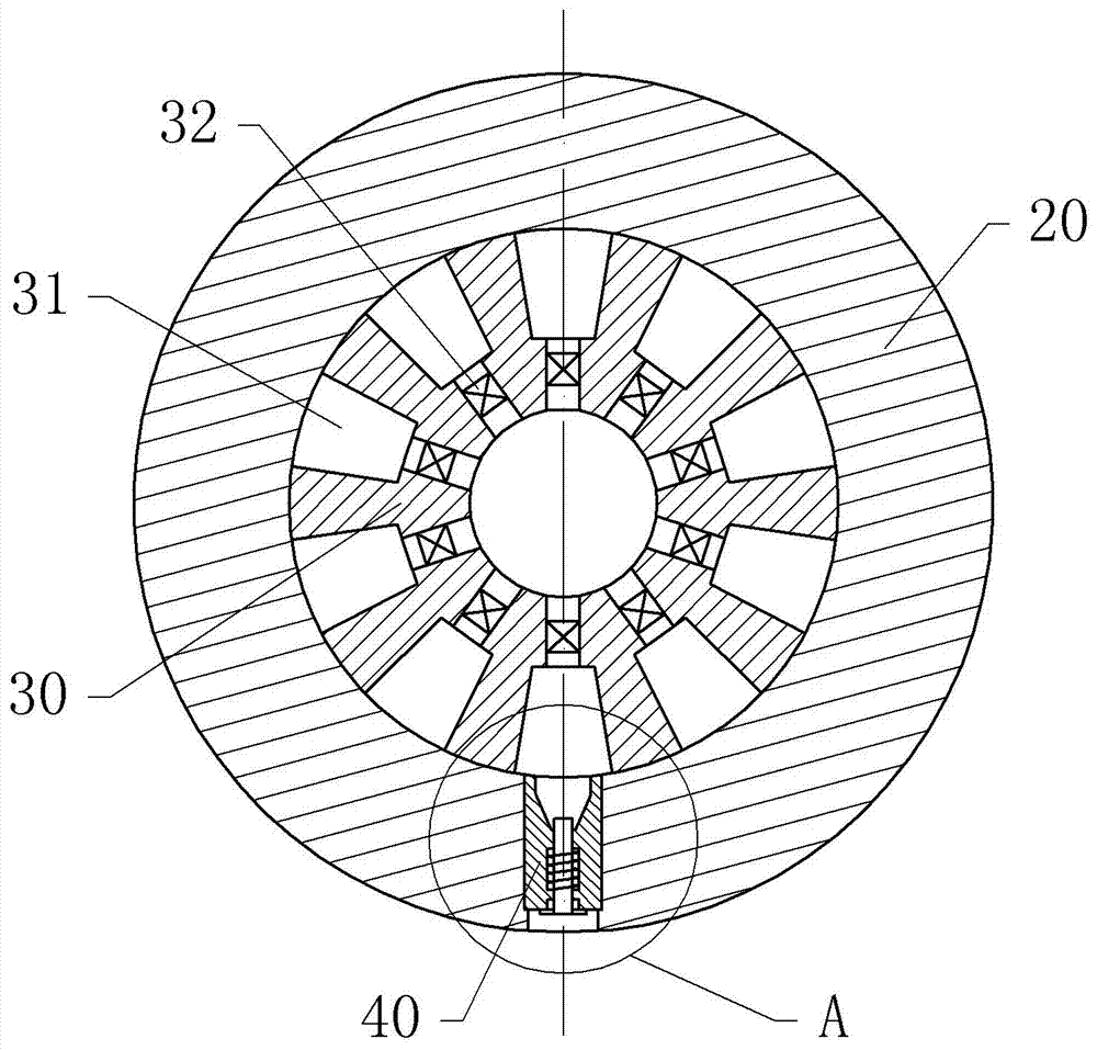
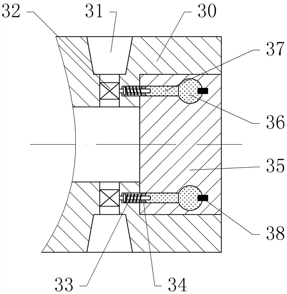
[0025] The reference signs in the drawings of the description include: frame 10, track 11, rack 12, transmission gear 13, die-cutting cylinder 20, air control shaft 30, air chamber 31, pressure reducing valve 32, pressure regulating spring 33, regulating valve Press block 34, pressure regulating disc 35, pressure chamber 36, channel 37, heat conduction block 38, adjustment mechanism 40, cylinder block 41, thimble 42, spring 43, rolling knife 44.

[0026] The embodiment is basically as figure 1 , figure 2 , image 3 and Figure 4 Shown:

[0027] The die-cutting device of this embodiment includes a frame 10, a die-cutting cylinder 20, a rolling knife 44, an adjustment mechanism 40, an air control shaft 30 and a pressure regulating mechanism. There are two parallel rails 11 on the frame 10. The middle part of the die-cutting cylinder 20 is located between the roller ta...


PUM


Abstract

The invention discloses a die-cutting device, which relates to the fields of printing and packaging; it includes a frame, a die-cutting cylinder, a rolling knife and an adjustment mechanism. The frame is provided with a guide rail and a rack parallel to the guide rail, and the die-cutting cylinder is slidably connected. On the track, the die-cutting cylinder is provided with a mounting hole along the radial direction of the die-cutting cylinder and through the side wall of the die-cutting cylinder. The rolling knife and the adjustment mechanism are installed in the mounting hole, and the air control shaft connected to the frame is also included. , the die-cutting cylinder is set outside the air control shaft, and the air control shaft is provided with an air inlet and a number of air chambers arranged radially along the air control shaft. One end of the air chamber is connected to the air inlet, and the air chamber is connected to the air inlet. There is a pressure reducing valve; the end of the air control shaft is fixed with a transmission gear that meshes with the rack; the adjustment mechanism includes a cylinder, a thimble located in the cylinder and a spring sleeved outside the thimble; one end of the cylinder can be Connected with the air chamber, the thimble can slide along the inner cavity of the cylinder body, and one end of the thimble is fixed with the rolling knife. The device can change the length of the cut on the packaging material.

Description

technical field [0001] The invention relates to the fields of printing and packaging, in particular to a die-cutting device. Background technique [0002] As the main equipment for realizing die-cutting and creasing, die-cutting machine plays an irreplaceable and important role in the packaging and printing industries. In the manufacturing process of the packaging bag, it is necessary to cut the packaging material to be made into the packaging bag first, and the cut packaging material can be folded to form a packaging bag. Therefore, when cutting the packaging material, it is necessary to cut the packaging material into sections, that is, it is necessary to reserve a folding part of the packaging material. [0003] The existing cutting method for packaging materials is mainly to use a roller for cutting. The roller is provided with an arc-shaped cutter. The arc length of the cutter is less than the circumference of the roller. The arc length of the cutter is the The length...

Claims


Application Information

Patent Timeline
IPC IPC(8): B31B70/20
Inventor 陈本发
Owner 瑞安市振华印刷机械加工有限公司
Learn More