Shell for electroacoustic transducers

A technology of electro-acoustic transducers and shells, applied in the direction of sensors, electrical components, etc., can solve problems such as failure to install normally, errors, fine-tuning of installation space, etc., and achieve the effect of increasing practical performance

Pending Publication Date: 2017-11-28
奥音科技(镇江)有限公司
View PDF10 Cites 0 Cited by
  • Summary
  • Abstract
  • Description
  • Claims
  • Application Information

AI Technical Summary

Problems solved by technology

Traditional electroacoustic transducers generally include a frame, a magnetic circuit system installed in the frame, a voice coil movably accommodated in the magnetic circuit system, and a diaphragm installed on the frame. The voice coil and diaphragm Connect to drive the diaphragm to vibrate to produce sound; the shell of the existing electro-acoustic transducer has limitations, and it cannot fine-tune the installation space, but there are certain errors in the process of reprocessing parts. If the error is too large, it will lead to the failure of normal installation, so in order to solve the above technical problems, it is particularly important to design a housing for electroacoustic transducers

Method used


Image

  • Shell for electroacoustic transducers
  • Shell for electroacoustic transducers

Examples


Embodiment Construction

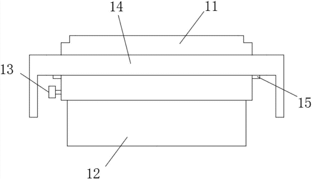
[0016] Such as figure 1 A housing applied to an electro-acoustic transducer shown includes a lower housing 12, an upper housing 11, a limit seat 15 and a protective cover 14, the lower housing 12 is a rectangular frame, and the The upper casing 11 is also a rectangular frame, the upper casing 11 is connected above the lower casing 12, and the bottom of the upper casing 11 is provided with a guide groove matching the upper end of the lower casing 12. The upper end of the lower housing 12 is movably connected in the guide groove, the lower housing 12 is connected with the upper housing 11 through a locking mechanism, and the limiting seat 15 is detachably connected to the upper housing 11. On the outer wall, a position-limiting seat 15 is respectively connected to both sides of the upper case 11, and the protective cover 14 is detachably connected to the outer side of the upper case 11, and the protective cover 14 is connected with the position-limiting The seats 15 are connect...


PUM


Abstract

The invention relates to a shell for electroacoustic transducers, which includes a lower shell, an upper shell, limiting seats, and a protective cover. The lower shell and the upper shell are rectangular boxes. The upper shell is connected above the lower shell. A guide slot matching the upper end of the lower shell is arranged in the bottom of the upper shell. The upper end of the lower shell is movably connected into the guide slot. The lower shell is connected with the upper shell through a locking mechanism. The limiting seats are detachably connected on the outer side wall of the upper shell. Each of the two sides of the upper shell is connected with one limiting seat. The protective cover is detachably connected to the outer side of the upper shell, and is connected with the limiting seats. The shell has the advantages of being simple in structure, easy to manufacture, and practical and efficient.

Description

technical field [0001] The invention relates to the technical field of electroacoustic transducers, in particular to a casing applied to electroacoustic transducers. Background technique [0002] An electroacoustic transducer is a device that converts electrical energy into sound energy, and is usually called a loudspeaker or horn. Traditional electroacoustic transducers generally include a frame, a magnetic circuit system installed in the frame, a voice coil movably accommodated in the magnetic circuit system, and a diaphragm installed on the frame. The voice coil and diaphragm Connect to drive the diaphragm to vibrate to produce sound; the shell of the existing electro-acoustic transducer has limitations, and it cannot fine-tune the installation space, but there are certain errors in the process of reprocessing parts. If the error is too large, it will lead to failure of normal installation, so it is particularly important to design a housing applied to the electroacousti...

Claims


Application Information

Patent Timeline
Patent Type & Authority Applications(China)
IPC IPC(8): H04R9/02
CPCH04R9/02H04R2420/00
Inventor 赵俊武尹德斌王路明历成宾贾广伟
Owner 奥音科技(镇江)有限公司
Why Eureka
Try Eureka