Air release regulating device for electronic sphygmomanometer

An electronic sphygmomanometer and regulating device technology, applied in the direction of vascular assessment, cardiac catheterization, etc., can solve the problem of insufficient deflation speed, aggravate the condition of patients with varicose veins, and cause danger, reduce pressure, and add automatic protection functions. , prevent dangerous effects

Active Publication Date: 2020-08-21
ANHUI POLYTECHNIC UNIV
View PDF12 Cites 0 Cited by
  • Summary
  • Abstract
  • Description
  • Claims
  • Application Information

AI Technical Summary

Problems solved by technology

[0003] (1) After the measurement is completed, the deflation adjustment device of the electronic sphygmomanometer currently used generally does not deflate fast enough. When the electronic sphygmomanometer fails unexpectedly and the pressure is too high, it is easy to cause danger, and it needs to be designed to deal with emergencies. deflation function;
[0004] (2) The deflation speed of the deflation adjustment device of the electronic sphygmomanometer in use cannot be adjusted, and the deflation speed required by different users may be different. Too slow or too fast deflation is not good for the health of the patient. If the air is too slow, the user's wrist will be held for too long, which is especially harmful to the health of patients with high blood pressure; if the air is too fast, the confining pressure of the wrist will drop sharply, which may aggravate the condition of patients with varicose veins over time;
[0005] (3) The deflation adjustment device of the electronic sphygmomanometer currently in use does not have a safety device when it is pressurized. If the pressurization speed is too fast, it may cause danger, and an automatic protection device should be installed.

Method used


Image

  • Air release regulating device for electronic sphygmomanometer
  • Air release regulating device for electronic sphygmomanometer

Examples


Embodiment

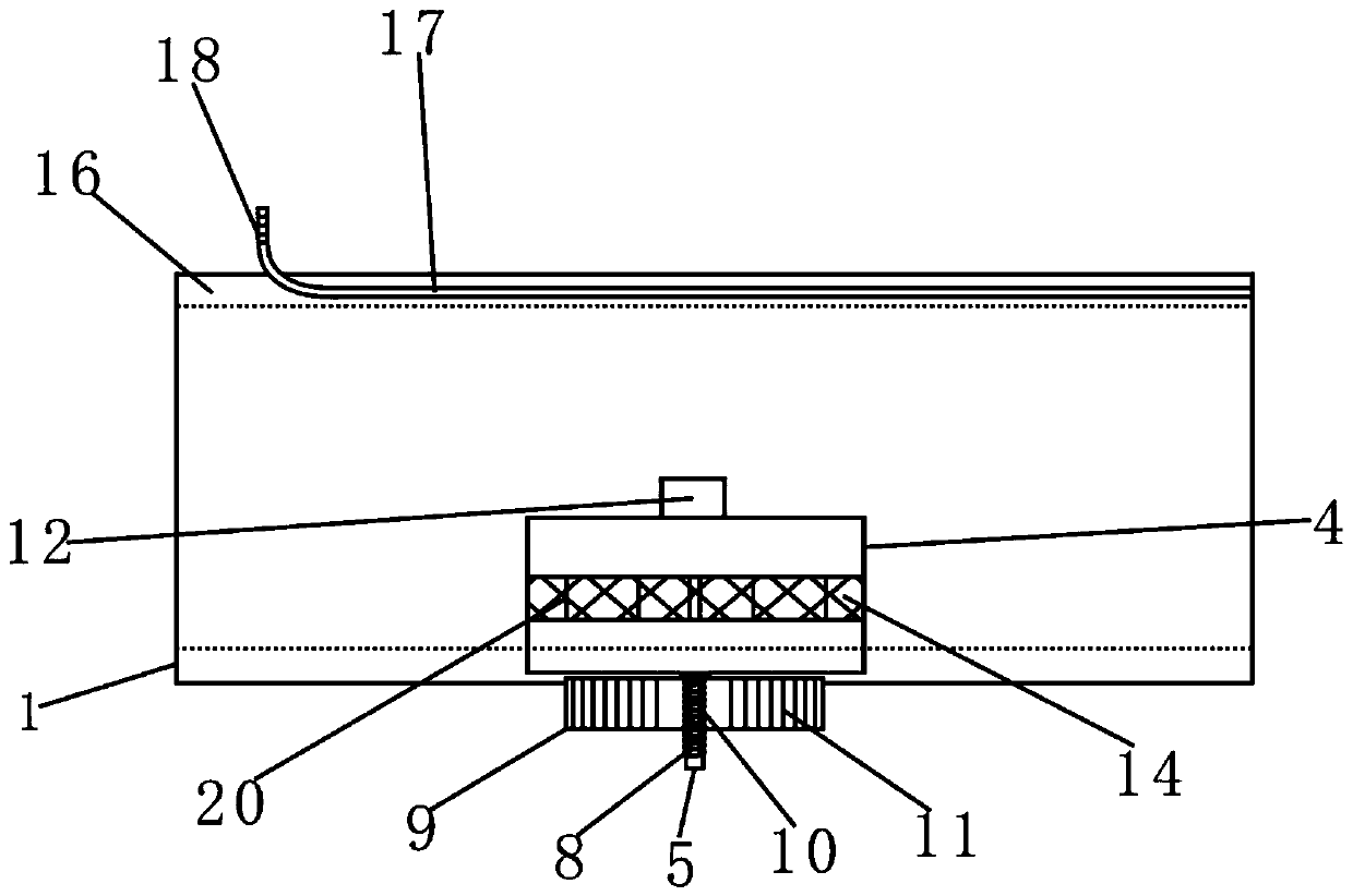
[0024] Such as figure 1 and figure 2 As shown, the present invention provides a deflation regulating device for an electronic sphygmomanometer, comprising an outer bladder 1 and an inner tank 2, the materials of the outer tank 1 and the inner tank 2 are high elastic silica gel, and the outer tank 1 is The surface is set in a zigzag shape that radiates outward. When the electronic sphygmomanometer is pressurized, the outer bladder 1 will expand outward under the pressure, and its outer surface is set in a zigzag shape to effectively prevent the outer bladder 1 from being under huge pressure. Explosion, the side of the outer bladder 1 is provided with an exhaust port 3, and the exhaust port 3 is set as a funnel shape with a wide left side and a narrow right side, and its side inclination angle is 60°. This shape is conducive to air flow from the left outer bladder 1 is exhausted into the deflation chamber 4, and it is not easy to block the exhaust port 3, or the backflow of ai...


PUM


Abstract

The invention discloses an air-bleeding regulation device of an electronic sphygmomanometer. The air-bleeding regulation device comprises an inner container and an outer container. The side of the outer container is provided with a nozzle, and an air bleeding chamber is fixedly connected to one side of the outer container, a bearing is arranged in the center of the bottom of the air-bleeding chamber, and a rotating shaft is connected to the inside of the bearing and connected with blades; the outer surface of the bearing is provided with thread; a regulating knob is arranged on the outer surface of the bearing; a groove with a downward opening is formed in the inner wall of the air-bleeding chamber at the top of the rotating shaft, and an elastic silicone block is arranged in the groove; an elastic silicone layer is fixedly connected to the top of the rotating shaft on the inner side of the air-bleeding chamber; the right side of the air-bleeding chamber is provided with an opening; a buffering rubber ring is fixedly connected to the left side of the outer container, a movable strip is arranged at the top of the outer container, and a drawing string is inset to the movable strip. With the arrangement of the rotating shaft, the regulating knob and the elastic silicone layer, air-bleeding speed of the electronic sphygmomanometer is realized; with the arrangement of the buffering rubber ring, an automatic protective function is added.

Description

technical field [0001] The invention relates to the technical field of electronic sphygmomanometers, in particular to a deflation adjustment device for electronic sphygmomanometers. Background technique [0002] Electronic sphygmomanometer is a medical device that uses modern electronic technology and the principle of indirect blood pressure measurement to measure blood pressure. Electronic sphygmomanometers are divided into arm type, wrist type, and watch type. Exhaust valve), the second generation (electronic servo valve), the third generation (pressurized synchronous measurement) and the fourth generation (integrated air circuit), the deflation adjustment device of the electronic sphygmomanometer currently in use has the following deficiencies at: [0003] (1) After the measurement is completed, the deflation adjustment device of the electronic sphygmomanometer currently used generally does not deflate fast enough. When the electronic sphygmomanometer fails unexpectedly ...

Claims


Application Information

Patent Timeline
Patent Type & Authority Patents(China)
IPC IPC(8): A61B5/022A61B5/0225
CPCA61B5/02233A61B5/0225
Inventor 倪维维
Owner ANHUI POLYTECHNIC UNIV
Why Eureka
Try Eureka