
Swing sole massage mechanism

A deceleration mechanism and component technology, applied in the direction of pneumatic massage, vibration massage, roller massage, etc., can solve the problems of uncomfortable massage, small massage force area, no occurrence, etc., and achieve a comfortable effect

Pending Publication Date: 2017-12-01
郑纯建
View PDF0 Cites 6 Cited by
  • Summary
  • Abstract
  • Description
  • Claims
  • Application Information

AI Technical Summary

Problems solved by technology

[0002] There are many types of massage equipment available, such as leg beauty machines, leisure chairs, massage chairs, etc., with the highest design goal of simulating human massage movements and massage effects, and are currently installed in massage equipment (such as beauty leg machines, massage chairs, etc.) to massage human legs The movements are all ordinary roller foot massagers. The massage force area is too small and the massage is very uncomfortable. At present, there is no foot massage mechanism for foot dynamic massage.

Method used


Image

  • Swing sole massage mechanism
  • Swing sole massage mechanism
  • Swing sole massage mechanism

Examples

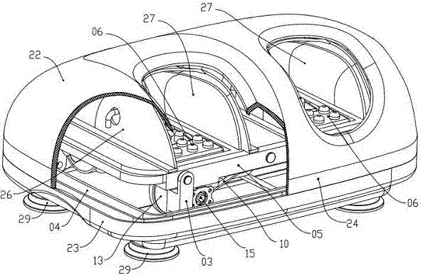
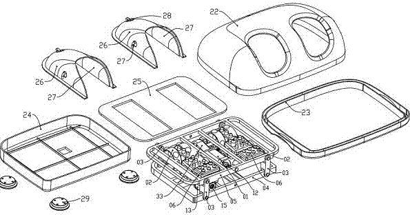
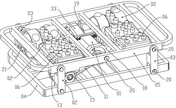

Embodiment Construction

[0025] The present invention will be further described below in conjunction with the accompanying drawings and specific embodiments.

[0026] refer to Figure 1~Figure 12 As shown, a swinging foot massage mechanism of the present invention includes two side connection holes 51 at the front and rear of the upper base 05 in the foot massage mechanism, and two side connection holes 51 at the front and rear of the lower base 04. Holes 41, the side connection holes 51,41 of the upper base 05 and the lower base 04 are respectively hinged with the holes 31 at both ends of the four elongated connecting columns 03, so that the upper base 05, the lower base 04, and the four connections The mutually hinged combination of columns 03 becomes a parallelogram, such as image 3 , Figure 4As shown; the lower side of one end of the upper base 05 is movably fixed with two bearing seats 15 with a shaking shaft 14, and a radial eccentric sleeve 16 and a large pulley 13 are fixed in the middle o...


PUM


Abstract

The invention discloses a swing sole massage mechanism. The swing sole massage mechanism comprises an upper base, a lower base and two connecting pillars, the upper base, the lower base and the connecting pillars are mutually hinged to form a parallelogram, a massage reducing mechanism is installed in the middle of the upper base, massage roller components are installed at the two sides of the massage reducing mechanism respectively, two sets of gasbag massage components are installed above the massage reducing mechanism, an upper shell and a middle shell are installed at the outer side of the massage reducing mechanism, a fixed slide cover is installed in the middle of the lower base, and a lower shell and foot pads are installed at the bottom side; a motor rotates positively to drive the upper base and the lower base to conduct parallel and transverse swing motion through the massage reducing mechanism, the motor rotates reversely to drive two massage plates at the two sides to conduct longitudinal high-frequency vibration on the soles of the human body, drives massage roller components which are installed at two ends of a long shaft to conduct massage motion, then through the combination of the gasbag massage components, the effect of conducting dynamic radiation and full-body massage on the legs of the human body is achieved, and the swing sole massage mechanism is small and exquisite in structural design, is better arranged in and applied to various massage leg-beautifying machines and massage armchairs.

Description

technical field [0001] The invention belongs to the field of massage appliances, and in particular relates to a leg and foot massage device, which is suitable for various types of leg massage and beautifying machines, and a built-in matching massage chair to realize multi-directional and comfortable foot massage. Background technique [0002] There are many types of massage equipment available, such as leg beauty machines, leisure chairs, massage chairs, etc., with the highest design goal of simulating human massage movements and massage effects, and are currently installed in massage equipment (such as beauty leg machines, massage chairs, etc.) to massage human legs The movements are all ordinary roller foot massagers. The massage force area is too small and the massage is very uncomfortable. At present, there is no foot massage mechanism for dynamic foot massage. Contents of the invention [0003] There is above-mentioned problem for existing technology, in order to impr...

Claims


Application Information

Patent Timeline
IPC IPC(8): A61H39/04A61H9/00A61H15/00A61H23/02
CPCA61H9/0078A61H15/0078A61H23/02A61H39/04A61H2015/0014A61H2201/1207A61H2205/125A61H2205/12
Inventor 郑纯建
Owner 郑纯建
Learn More