Air blower control circuit with diagnostic function

A technology of control circuit and diagnostic function, which is applied in pump control, mechanical equipment, machine/engine, etc., can solve the problem of high design cost and achieve the effect of saving development cost

Active Publication Date: 2017-12-01
WENZHOU CHANGJIANG AUTOMOBILE ELECTRONICS SYST
View PDF5 Cites 6 Cited by
  • Summary
  • Abstract
  • Description
  • Claims
  • Application Information

AI Technical Summary

Problems solved by technology

But such a design costs more

Method used


Image

  • Air blower control circuit with diagnostic function
  • Air blower control circuit with diagnostic function
  • Air blower control circuit with diagnostic function

Examples


Embodiment Construction

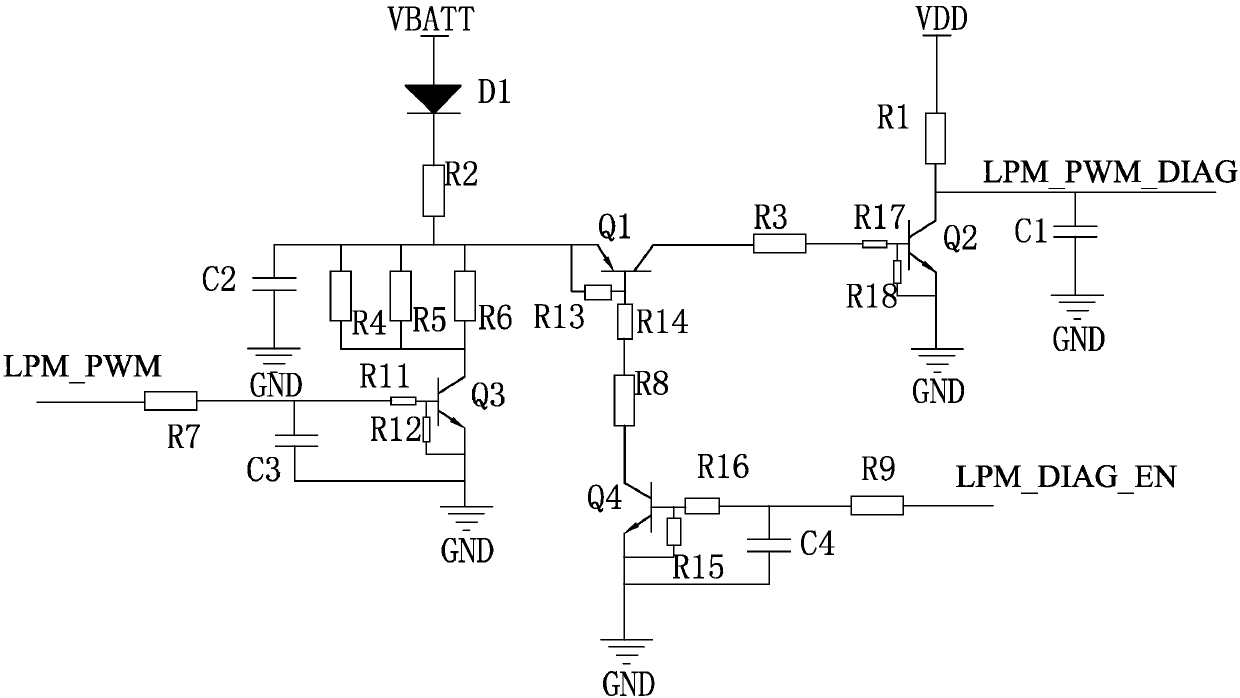
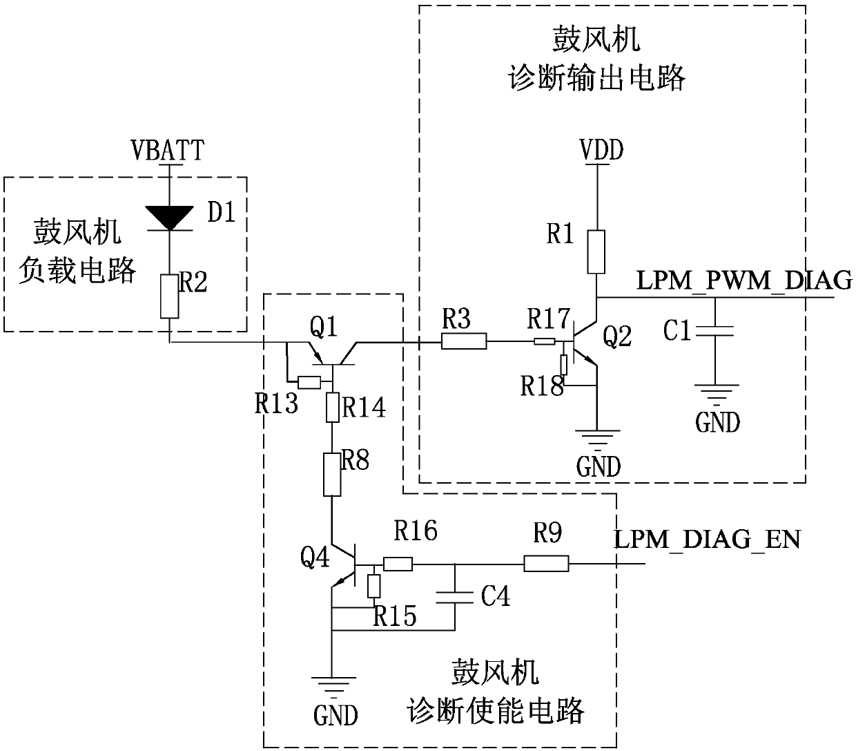
[0016] like Figure 1-3 As shown, the LPM circuit can be divided into: blower external load, blower low-side control circuit and blower diagnostic circuit.

[0017] The blower drive circuit is built with discrete components. The software only needs to control the duty cycle of the LPM_PWM terminal and capture the duty cycle of LPM_PWM_DIAG (requires the corresponding MCU-IO port to have the capture function) to realize the blower output function and the blower output port diagnostic function.

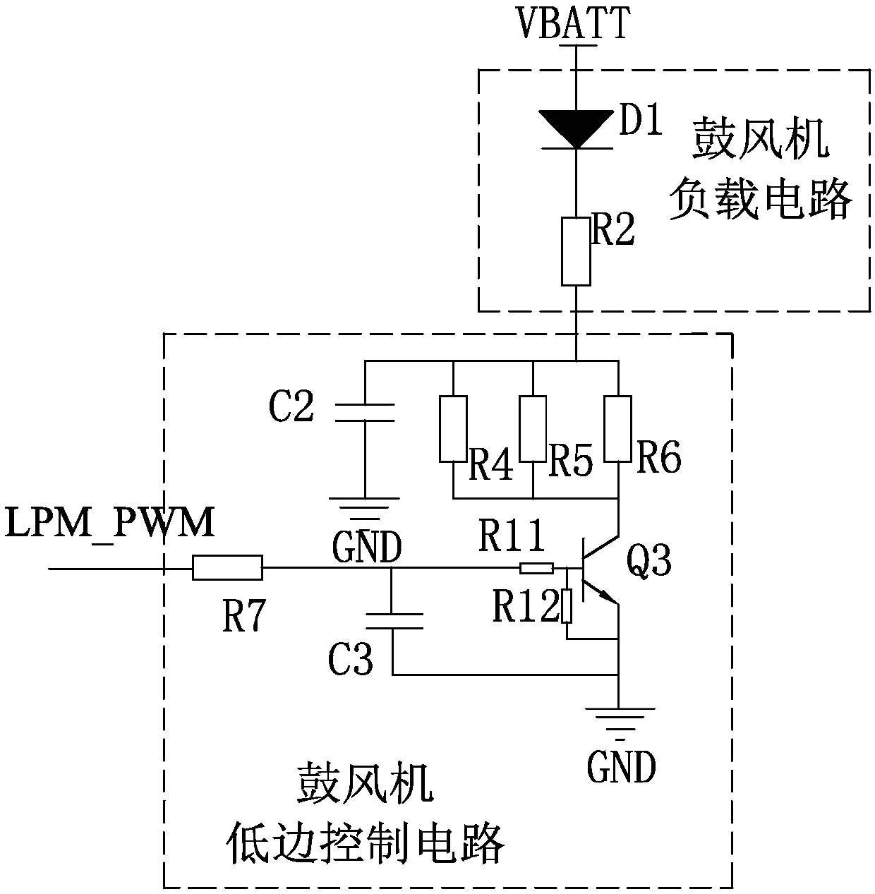
[0018] The working principle of the blower external load circuit:

[0019] The blower load circuit includes power supply voltage VBATT, diode D1 and resistor R2. The anode of diode D1 is connected to the power supply voltage VBATT, and resistor R2 is connected to the cathode of diode D1. The resistance R2 is 4.64KΩ. The type of diode D1 is 1SR154 (maximum positive current 1A).

[0020] Working principle diagram of blower low-side control circuit:

[0021] The blower low-side control...


PUM


Abstract

The invention discloses an air blower control circuit with a diagnostic function. The air blower control circuit comprises an air blower loading circuit. The air blower loading circuit comprises a power voltage VBATT, a diode D1 and a resistor R2. The positive pole of the diode D1 is connected to the power voltage VBATT. The resistor R2 is connected to the negative pole of the diode D1. The resistor R2 is connected with an air blower low-side control circuit and an air blower diagnostic circuit. The air blower control circuit has the beneficial effects that the development cost is saved greatly, the capturing function of a MCU-IO port is adopted, and the diagnostic function of an LPM output function and an LPM output port is achieved. The design is suitable for the PWM output circuit design with the similar diagnosis requirement.

Description

technical field [0001] The invention relates to the technical field of automobile electronics, in particular to a blower control circuit suitable for automobile electronics and having a diagnosis function. Background technique [0002] The blower PWM signal (hereinafter referred to as LPM) output is used to control the blower load on the air conditioning box, and the air conditioning wind power can be adjusted by adjusting the LPM duty cycle. At present, the air conditioner controller on the vehicle generally requires short-circuit and open-circuit diagnosis for the output port. Therefore, the LPM output diagnosis on the air conditioner controller is particularly important. [0003] General circuit design requirements are realized. LPM outputs short power supply, short ground, and open circuit diagnosis. The usual design method is to use smart low-side tubes to achieve. MCU communicates with smart low-side tubes through SPI and other interfaces to monitor whether the output...

Claims


Application Information

Patent Timeline
Patent Type & Authority Applications(China)
IPC IPC(8): F04D27/00
CPCF04D27/001
Inventor 叶增鸿黄成发叶豪杰彭时翔曾贵富
Owner WENZHOU CHANGJIANG AUTOMOBILE ELECTRONICS SYST
Why Eureka
Try Eureka