
Centrifugal compressor inlet guide blade structure with low flow losses under prewhirl condition

A technology of centrifugal compressors and inlet guide vanes, applied in the field of compressors, can solve problems such as separation loss, achieve the effects of expanding blocked flow, suppressing separation flow loss, and improving the effect

Active Publication Date: 2017-12-01
XI AN JIAOTONG UNIV
View PDF6 Cites 0 Cited by
  • Summary
  • Abstract
  • Description
  • Claims
  • Application Information

AI Technical Summary

Problems solved by technology

[0005] The object of the present invention is to provide a centrifugal compressor inlet guide vane structure with low flow loss under the pre-rotation condition, to overcome the separation loss of the inlet guide vane blade and the separation loss on the near-wheel disk surface produced under the pre-rotation condition, and at the same time suppress Mismatch between the flow at the outlet of the guide vane and the structure of the inlet of the vane under the pre-rotation condition

Method used


Image

  • Centrifugal compressor inlet guide blade structure with low flow losses under prewhirl condition
  • Centrifugal compressor inlet guide blade structure with low flow losses under prewhirl condition
  • Centrifugal compressor inlet guide blade structure with low flow losses under prewhirl condition

Examples


Embodiment Construction

[0034] The present invention will be described in further detail below in conjunction with the accompanying drawings. It should be understood that the specific embodiments described here are only for explaining the present invention, and are not intended to limit the present invention.

[0035] Symbol meaning among the figure of the present invention is:

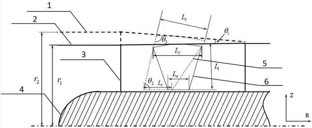
[0036] θ 1 ——cone angle of the inlet air duct connecting with the inlet guide vane, °;

[0037] θ 2 ——the angle between the leading edge of the inlet guide vane and the blade bottom, °;

[0038] θ 3 ——the angle between the leading edge of the inlet guide vane and the tangent line at the midpoint of the blade tip arc, °;

[0039] L 1 ——Height of original inlet guide vane, mm;

[0040] L 2 ——The top chord length of the original inlet guide vane, mm;

[0041] L 3 ——Top chord length of the improved inlet guide vane, mm;

[0042] L 4 ——The bottom chord length of the original inlet guide vane, mm;

[0043] L 5 ——The b...


PUM


Abstract

The invention discloses a centrifugal compressor inlet guide blade structure with low flow losses under the prewhirl condition. Original inlet guide blades are determined; the chord lengths of the bottoms of improved guide blades are determined according to the chord length ratio of L5 / L4, the improved guide blades are horizontally moved in the R direction along guide blade wing-section center lines, the front edges of the inlet guide blades form the backward sweep of theta2 relative to the blade bottoms, and thus the front edge positions of the improved guide blades can be determined; the molded line of an original air inlet channel connected with the inlet guide blades is rotated in a clockwise mode at the angle of theta1, and an inlet of the improved air inlet channel is in a horn shape; and the chord lengths of the tops of the improved guide blades are determined according to the chord length ratio of L3 / L2, the improved guide blades are moved upwards to the improved air inlet channel wall surface along the front edge lines of the improved guide blades, and the included angle between the front edges of the inlet guide blades and the tangent line of the arc line midpoints of the blade tops can meet the condition that theta3 is equal to 180 degrees-theta2-theta1. By the adoption of the centrifugal compressor inlet guide blade structure, separation flow losses of the blade surfaces and the close wheel disk sides can be restrained, the centrifugal compressor inlet guide blade structure is suitable for a wide flow range and prewhirl angle range, the complete machine variable efficiency and overall pressure ratio of the centrifugal compressor can be effectively improved and meanwhile the blocking flow amount within the working condition range can be increased obviously.

Description

technical field [0001] The invention relates to the technical field of compressors, in particular to an improved inlet guide vane and inlet air intake structure, in particular to a centrifugal compressor inlet guide vane structure with low flow loss under pre-rotation conditions, which is suitable for centrifugal compressor working conditions Range prespin adjustment process. Background technique [0002] The performance curve of the centrifugal compressor can be shifted by adjusting (pre-rotating) the inlet guide vane, so that the working point can be shifted to a certain range from the initial working condition without pre-rotating, so as to achieve a smaller or larger flow rate. The purpose of running down. However, as the pre-swirl angle increases, the flow loss in the inlet section will also increase significantly. The research shows that, especially at a large pre-rotation angle, the flow loss caused by the traditional inlet guide vane shape occupies a relatively hig...

Claims


Application Information

Patent Timeline
IPC IPC(8): F04D29/44
CPCF04D29/441
Inventor 赵家毅席光
Owner XI AN JIAOTONG UNIV
Learn More