
Intelligent supporting device for emergency safety of large smart city industrial building elevator

A technology for industrial buildings and support devices, applied in the directions of transportation, packaging, elevators, etc., can solve the problems of loosening of the support structure, the impact of the shock resistance of the support structure on the operation safety, etc. damage effect

Inactive Publication Date: 2017-12-08
GUANGDONG ADWAY CONSTR (GRP) HLDG CO LTD
View PDF8 Cites 0 Cited by
  • Summary
  • Abstract
  • Description
  • Claims
  • Application Information

AI Technical Summary

Problems solved by technology

[0003] The existing elevator guide rails usually move along the brackets installed in the elevator shaft. During the operation of the elevator, vibrations will be generated, and the vibrations will be transmitted to the brackets through the guide rails, making the bracket structure easy to loosen. The shock resistance of the bracket structure affects its operation safety.

Method used


Image

  • Intelligent supporting device for emergency safety of large smart city industrial building elevator

Examples


Embodiment 1

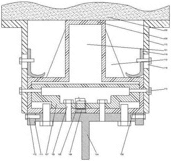
[0019] Such as figure 1 As shown, an intelligent support device for emergency safety of elevators in large-scale smart city industrial buildings includes a hollow support 101, the cross section of the support 101 is T-shaped, and one end of the T-shaped bottom 105 of the support 101 is fixed Connected to the elevator shaft wall 102, one end of the T-shaped top 106 is connected to the T-shaped guide rail 104 by bolts, the inner side of the T-shaped top 106 is provided with a connecting section 107, and the T-shaped top 106 is provided with a passage Holes, the first fixing bolt 103 passing through the connecting section 107 is provided on the connecting section 107, and the threaded hole corresponding to the position of the through hole is provided on the T-shaped guide rail 104, The first fixing bolt 103 passes through the connecting section 107 and the through hole on the T-shaped top 106 in turn and is screwed on the T-shaped guide rail 104, and on both sides of the bracket ...

Embodiment 2

[0022] This embodiment is based on Embodiment 1. In order to make the support structure have better impact resistance, in this embodiment, preferably, the middle part of the T-shaped top 106 is open, and the length direction of the opening is parallel to In the length direction of the bracket 101, a groove 108 is provided on one opening, and a positioning plate 109 is provided on the opposite opening, and the positioning plate 109 can be embedded in the groove 108, so The length H of the positioning plate 109 is less than or equal to the depth h of the groove 108 .

[0023]In this embodiment, in order to support the bracket, in this embodiment, preferably, a reinforcing rib 110 is provided on the side of the T-shaped top 106 away from the T-shaped guide rail 104, and the reinforcing rib 110 is One end of the rib 110 is connected to the T-shaped top 106 , and the other end of the reinforcing rib 110 is fixedly connected to the side wall of the T-shaped bottom 105 .

[0024] In...


PUM


Abstract

The invention discloses a supporting device for emergency safety of a large smart city industrial building elevator. The supporting device comprises a hollow support. The cross section of the support is in a T shape. One end of the T-shaped bottom of the support is fixedly connected to the elevator shaft wall, and one end of the T-shaped top of the support is connected with a T-shaped guide rail through a bolt. A connecting section is arranged on the inner side of the T-shaped top. A through hole is formed in the T-shaped top. The connecting section is provided with a first fixing bolt penetrating the connecting section. Supporting parts are arranged on the two sides of the support correspondingly. One end of each supporting part is fixedly connected to the elevator shaft wall. The end, away from the elevator shaft wall, of each supporting part is attached to the side wall of the T-shaped top. The cross section of the connecting section is of a hollow T-shaped structure. The hollow support structure is adopted in the supporting device, and the supporting device has better impact resisting capability; and the supporting part structure is adopted, the support structure can be supported and can be prevented from deforming, and the integral structure has better stability.

Description

[0001] This application is a divisional application of a patent application with the application number 201610084635.3 and the title of the invention is a support device for emergency safety of elevators in large-scale smart city industrial buildings. technical field [0002] The invention relates to an intelligent support device for the emergency safety of industrial building elevators in a large smart city. Background technique [0003] The existing elevator guide rails usually move along the brackets installed in the elevator shaft. During the operation of the elevator, vibrations will be generated, and the vibrations will be transmitted to the brackets through the guide rails, making the bracket structure easy to loosen. The shock resistance of the bracket structure affects its operation safety. . Contents of the invention [0004] The purpose of the present invention is to provide an intelligent support device for the emergency safety of elevators in large-scale smart...

Claims


Application Information

Patent Timeline
Patent Type & Authority Applications(China)
IPC IPC(8): B66B7/02
CPCB66B7/023B66B7/028
Inventor 朱明德李成
Owner GUANGDONG ADWAY CONSTR (GRP) HLDG CO LTD
Learn More