Optimized deep groove ball bearing

A ball bearing and bearing technology, applied in the direction of bearing components, shafts and bearings, bearing assembly, etc., can solve the problems of inconvenient installation of bearings, installation methods, single angles, and inability for non-technical personnel to install bearings, etc. Retracted, easy-to-install effect

Active Publication Date: 2017-12-08
NINGBO KAILI HI TECH BEARING CO LTD
View PDF8 Cites 4 Cited by
  • Summary
  • Abstract
  • Description
  • Claims
  • Application Information

AI Technical Summary

Problems solved by technology

[0004] The purpose of the present invention is to solve the disadvantages of the prior art, such as the inconvenience of installing the bearing during use, the inability of non-technical personnel to install it, and the shortcomings of the existing bearing, the installation method and the single angle, so as to propose an optimized deep groove ball bearing

Method used


Image

  • Optimized deep groove ball bearing
  • Optimized deep groove ball bearing
  • Optimized deep groove ball bearing

Examples


Embodiment 1

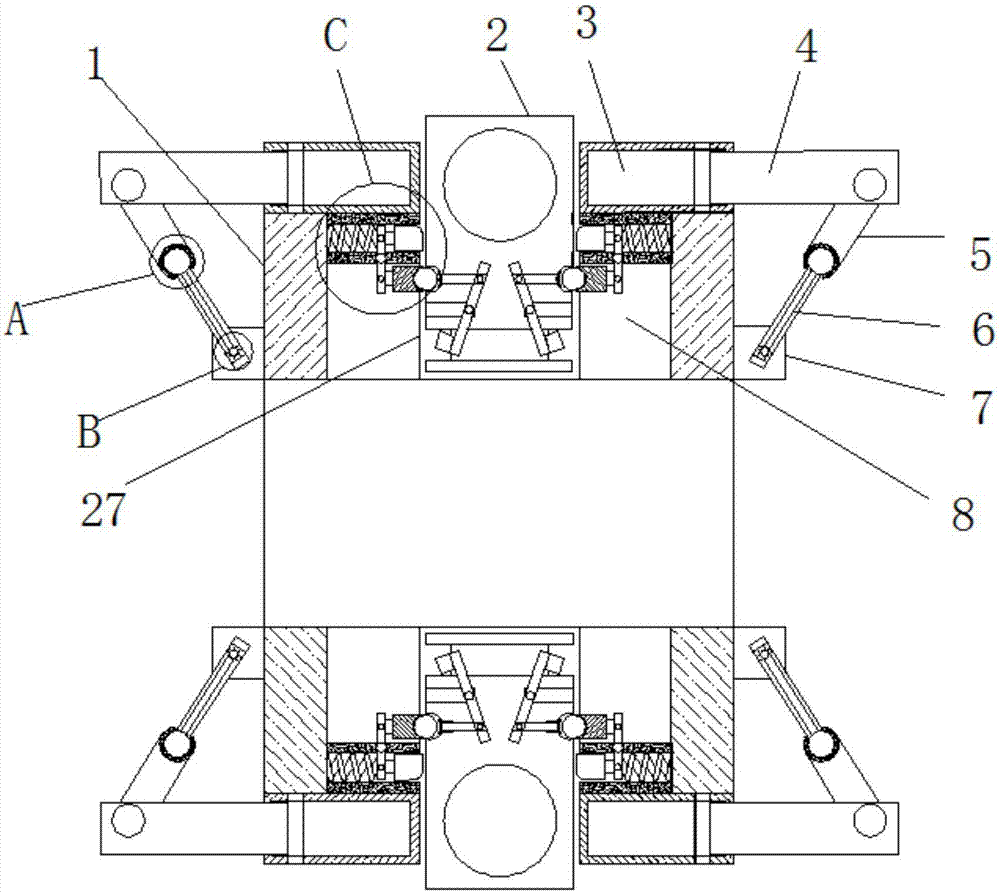
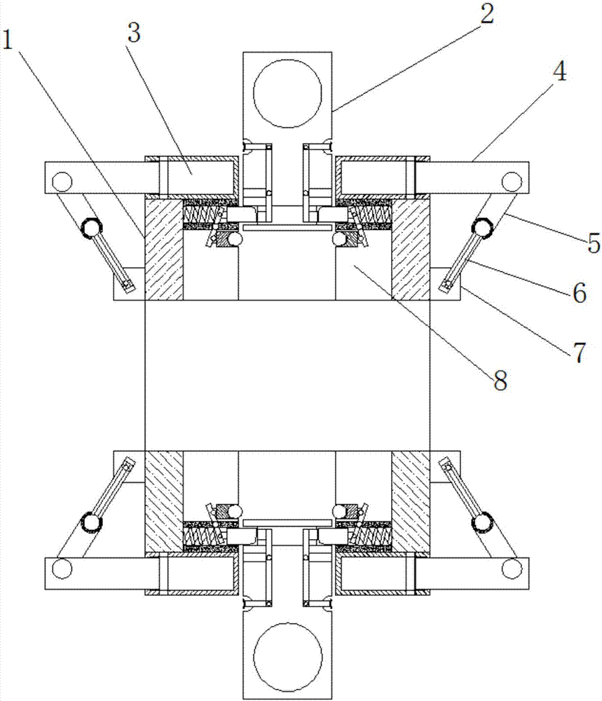
[0033] refer to Figure 1-6, an optimized deep groove ball bearing, including a bearing head 1 and a bearing inner ring. Rolling bodies are arranged on the sides of the rings that are close to each other, and fixing devices are arranged on both sides of the bearing head 1. The fixing devices include connecting kits, expansion slots 3, extension rods 4 and movable kits. The end of the bearing head 1 away from the inner ring of the bearing is provided with There are two telescopic grooves 3, and the two telescopic grooves 3 are arranged on both sides of the bearing head 1, and the ends of the telescopic grooves 3 away from each other are provided with an opening, and the opening is movably connected with a stretch rod 4, and one end of the stretch rod 4 is connected from the The opening of the telescopic groove 3 moves into the telescopic groove 3, and the other end of the extension rod 4 is provided with a connecting kit, which is composed of a live rod 5, a first circular groo...

Embodiment 2

[0036] A cavity 27 is provided in the middle position of the bearing head 1, and the cavity 27 is arranged in the middle position of the two groups of telescopic grooves 3 in the bearing head 1, and one end of the cavity 27 passes through the bearing head 1, and an opening is provided, and the opening is arranged in On the end of the bearing head 1 away from the inner ring of the bearing, an adjustment cavity 8 is provided on both sides of the inner cavity 27 of the bearing head 1, and a limit fixing mechanism is arranged on the side of the adjustment cavity 8 close to the telescopic groove 3. The limit fixing mechanism includes The fixed frame 21, the second balance bar 20, the spring 22, the locking block 19 and the rotation limiting mechanism, the fixed frame 21 is fixedly arranged on the side away from the bearing inner ring on the adjustment chamber 8, and the fixed frame 21 is close to the cavity 27 One side is provided with an opening, the opening passes through the cavi...

Embodiment 3

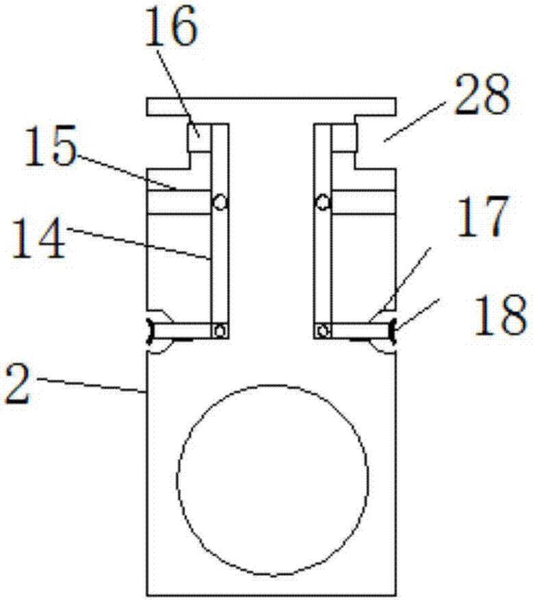
[0039] The cavity 27 is provided with a movable fixing part 2, and the both sides of the fixing part 2 are provided with a limiting groove 17 and a locking groove 28, and the fixing part 2 is provided with a fixed through hole on the side away from the limiting groove 17, and the fixed part The through hole is arranged on the end of the fixing part 2 away from the cavity 27, and one side of the fixing part 2 is provided with a locking groove 28, and the locking groove 28 is arranged on both sides of the end of the fixing part 2 extending into the cavity 27, limiting The position groove 17 is opened in the middle position of the fixing part 2, and the side of the limit groove 17 close to each other is movably provided with a limit plate 18, and the limit plate 18 moves through the limit groove 17, and the limit groove in the fix part 2 17 and the locking groove 28 is provided with a first balance bar 14, and the middle position of the first balance bar 14 is movably connected wi...


PUM


Abstract

The invention belongs to the technical field of bearings, in particular to an optimized deep groove ball bearing. The disadvantages that the bearing is uneasy to install in use, and can not be installed by non-technical personnel, and an existing bearing is single in installation method and angle in the prior art are overcome; thus, the invention provides the optimized deep groove ball bearing. According to the following solution, the optimized deep groove ball bearing comprises a bearing head and a bearing inner ring; the bearing inner ring is of an circular structure, and the outer side of the bearing inner ring is provided with the bearing head along the shape of the outer side; and the sides, approaching to each other, of the bearing head and the bearing inner ring are provided with rolling bodies, and both sides of the bearing head are provided with fixing devices. The optimized deep groove ball bearing provided by the invention is novel in structure, and the fixing devices are arranged at both sides, which can effectively help users select fixed directions according to different conditions; the use convenience of the bearing and the using effect of the optimized deep groove ball bearing are improved, so that multiple directions can be selected during installation of the bearing, and the bearing can be installed by the non-technical personnel.

Description

technical field [0001] The invention relates to the technical field of bearings, in particular to an optimized deep groove ball bearing. Background technique [0002] Bearing is an important part of contemporary mechanical equipment. Its main function is to support the mechanical rotating body, reduce the friction coefficient during its movement, and ensure its rotation accuracy. According to the different friction properties of moving elements, bearings can be divided into rolling bearings There are two types of rolling bearings and sliding bearings. Among them, rolling bearings have been standardized and serialized, but compared with sliding bearings, their radial size, vibration and noise are larger, and their prices are also higher. Rolling bearings generally consist of outer rings, inner rings, rolling elements and The cage consists of four parts. According to the shape of the rolling body, rolling bearings are divided into two categories: ball bearings and roller beari...

Claims


Application Information

Patent Timeline
Patent Type & Authority Applications(China)
IPC IPC(8): F16C43/04F16C41/00
CPCF16C41/00F16C43/04
Inventor 卢文立王应毅周士蛟
Owner NINGBO KAILI HI TECH BEARING CO LTD
Why Eureka
Try Eureka