DC quick fuse for electric vehicle

A technology of electric vehicles and fuses, which is applied in the direction of circuits, electrical components, emergency protection devices, etc., can solve problems such as protection malfunction, system protection, decomposition failure, etc., and achieve the effect of fast action speed, large rated current, and simple process

Active Publication Date: 2017-12-08
杭州布雷科电气有限公司
View PDF9 Cites 2 Cited by
  • Summary
  • Abstract
  • Description
  • Claims
  • Application Information

AI Technical Summary

Problems solved by technology

However, the existing fuses have the following problems when they are used for the protection of high-voltage circuits of electric vehicles: when using low-overload characteristic fuses, the fuses are likely to cause protection malfunctions during the acceleration phase of the vehicle because they cannot withstand the overcurrent during acceleration; In the case of an overload characteristic fuse, due to the excessive size of the narrow neck, the breaking time is too long in the case of a small short-circuit fault, and the system cannot be protected in time.
[0004] The hybrid current-limiting fuse uses an explosive bridge high-speed breaker and an arc-extinguishing fuse in parallel to solve the contradiction between the current flow and breaking speed of the fuse, and can quickly detect various faults in combination with an electronic controller, but the explosive bridge high-speed The breaker is driven by explosives, and there are the following problems in practical applications: 1) The life of explosives is limited, and it will gradually decompose and fail with the increase of use time; 2) Explosives and other pyrotechnics are expensive; 3) The requirements for ambient temperature are harsh
At the same time, the electronic control system also has the possibility of refusal and malfunction, and the protection reliability is not high.

Method used


Image

  • DC quick fuse for electric vehicle
  • DC quick fuse for electric vehicle
  • DC quick fuse for electric vehicle

Examples


Embodiment Construction

[0021] The following will clearly and completely describe the technical solutions in the embodiments of the present invention with reference to the accompanying drawings in the embodiments of the present invention. Obviously, the described embodiments are only some, not all, embodiments of the present invention. Based on the embodiments of the present invention, all other embodiments obtained by persons of ordinary skill in the art without making creative efforts belong to the protection scope of the present invention.

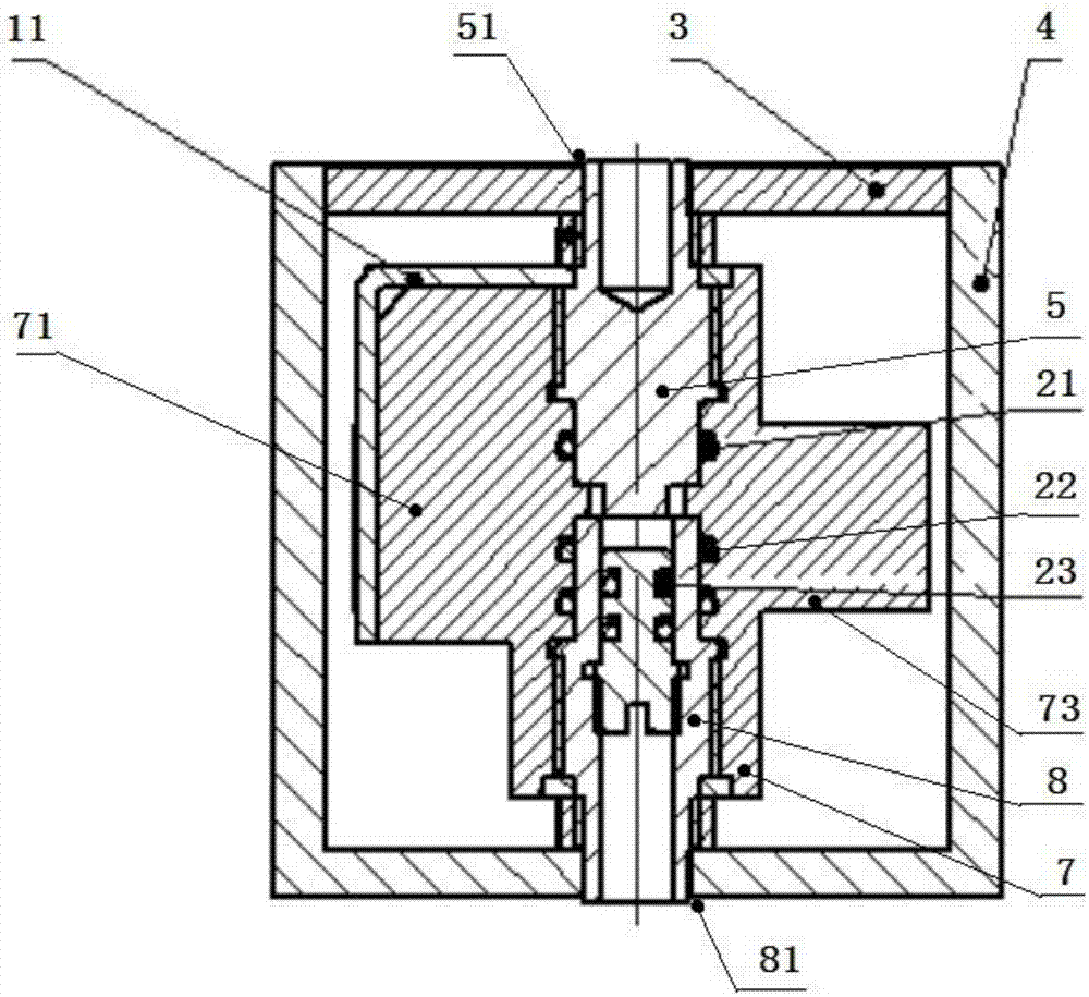
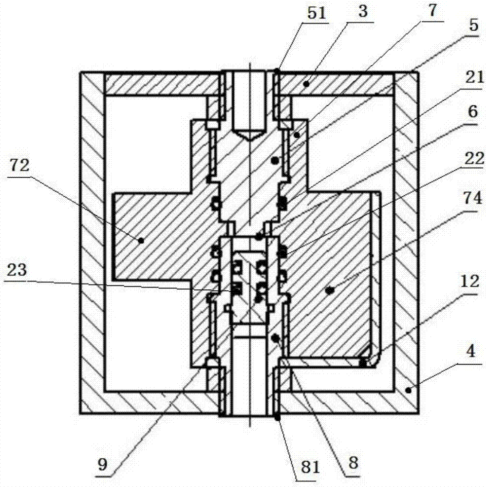
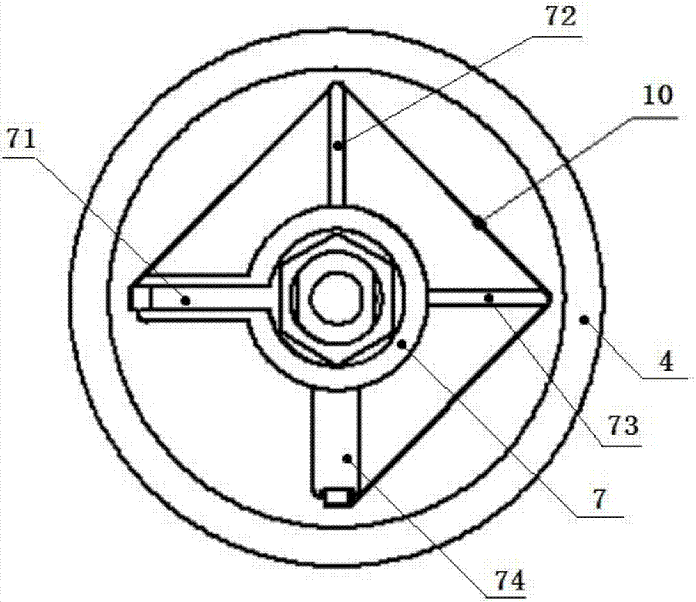
[0022] Depend on Figure 1-3 As shown, a DC fast fuse for an electric vehicle in this embodiment includes a cylindrical shell 4, an internal fixing frame is arranged in the casing 4, and a copper pole is arranged in the internal fixing frame 7, and the copper pole includes a contact connection The upper copper pole 5 and the lower copper pole 8 are welded and installed with a flow-through fuse 6 between the upper copper pole 5 and the lower copper pole 8. The ...


PUM


Abstract

The invention discloses a DC quick fuse for an electric vehicle. The DC quick fuse comprises a housing which is internally provided with an inner fixing rack. The inner fixing rack is internally provided with a copper pole column. The copper pole column comprises an upper copper pole and a lower copper pole which are connected with each other in a contacting manner. A current flow fuse is welded between the upper copper pole and the lower copper pole. The lower copper pole is internally provided with a lower copper pole chamber which is through in the vertical direction. The lower copper pole chamber is internally provided with a piston which moves vertically. An arc extinguishing fuse is welded on the inner fixing rack. The upper copper pole, the lower copper pole, the inner fixing rack and the piston form a small chamber which is filled with insulating oil. The part surrounding the current flow fuse is filled with the insulating oil. Quartz sand is filled between the housing and the inner fixing rack. The part surrounding the arc extinguishing fuse is filled with the quartz sand. The DC quick fuse for the electric vehicle is advantageous in that 1, compared with a common fuse, large rated current, low power consumption and high action speed are realized; and compared with an explosive bridge type mixed current limiting fuse, simple process, low cost and high reliability are realized.

Description

technical field [0001] The invention relates to the field of fuses, in particular to a DC fast fuse for electric vehicle protection. Background technique [0002] The fuse is an electrical appliance that plays a role in safety protection in the power system. It can be widely used in various systems as the protection of the power grid and electrical equipment. When a short circuit or overload fault occurs in the line of the grid or electrical equipment, the fuse It can automatically cut off the circuit to avoid damage to electrical equipment and prevent accidents from spreading. [0003] Ordinary fuses are composed of metal melt, shell and quartz sand and other filling materials, among which the melt is the key component to control the characteristics of the fuse. The fuses with different protection characteristics can be obtained by designing different melt neck structures and sizes. However, the existing fuses have the following problems when they are used for the protecti...

Claims


Application Information

Patent Timeline
Patent Type & Authority Applications(China)
IPC IPC(8): H01H85/12H01H85/18
CPCH01H85/12H01H85/18
Inventor 杨柳戴超
Owner 杭州布雷科电气有限公司
Why Eureka
Try Eureka