Self-locking hook wire clamp

A wire hooking and self-locking technology, which is applied in the direction of the cable suspension device, can solve the problems of cable overheating, low street code efficiency, time-consuming and labor-intensive problems, and achieve the effect of not easy to loosen, simple structure and convenient use

Active Publication Date: 2017-12-08
广州勇艺邦电子科技有限公司
View PDF8 Cites 4 Cited by
  • Summary
  • Abstract
  • Description
  • Claims
  • Application Information

AI Technical Summary

Problems solved by technology

The traditional street code consists of a hardware bracket that can be nailed to the wall (the hardware bracket includes a base that can be fixed to the wall and a bracket that can be fixed with a binding wire), a porcelain lug for supporting cables, and a porcelain lug for fixing the porcelain lug to the hardware. The cable on the bracket is composed of wires. When the cable crosses the street, it is generally close to the porcelain, and then the cable and the porcelain are bound and fixed by winding the cable. This kind of street code is inefficient, and the binding method and binding tightness are not uniform. Standard, large randomness, easy to cause loose wires, loose or even loose after long-term use, usually use thinner metal wires such as aluminum wires, which are directly wound on the cable sheath, which will cause damage to the cable sheath , it is easy to cause dangers such as cable overheating or even leakage short circuit, and the insulated cable will be in direct contact with the metal wire, resulting in potential leakage
[0003]The existing technology has improved the traditional cable fixing method, and the cable is fixed on the porcelain by using the clamp, but these clamps generally adopt the method of bolts and nuts To connect, when working at heights, it is time-consuming and labor-intensive for a single person to operate

Method used


Image

  • Self-locking hook wire clamp
  • Self-locking hook wire clamp

Examples


Embodiment Construction

[0021] A self-locking fastening clamp of the present invention will be further described below in conjunction with the accompanying drawings:

[0022] It should be noted that the terms "upper", "lower", "front", "rear" and similar expressions used in this specification are only for the purpose of illustration, and are determined according to the actual situation in the embodiment; "Porcelain Lu" can be selected from the current common street code porcelain or similar structures.

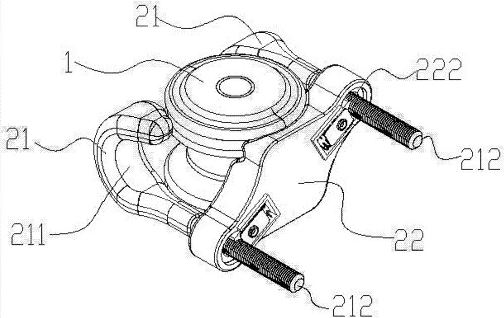
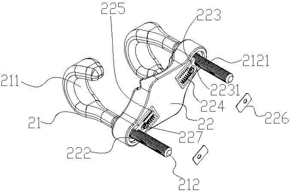
[0023] Such as Figure 1-2 As shown, it includes a splint 22 and two J-shaped clips 21. The bending part of the J-shaped clip 21 is a clamping part 211, and the side bar is a locking rod 212. The splint 22 is provided with two corresponding locking rods 212. Two locking holes 222, two J-shaped clamps 21 are diagonally arranged on the splint 22 and their hooks are opposite, and its locking rods 212 pass through the locking holes 222 on the splint 22 vertically respectively, and the locking rods 212 a...


PUM


Abstract

The invention discloses a self-locking hook wire clamp. The self-locking hook wire clamp comprises a clamping plate and two J-shaped clamps, wherein the two J-shaped clamps are arranged on the clamping plate in opposite angles and hooks of the two J-shaped clamps are opposite, locking levers vertically pass through locking holes in the clamping plate respectively, a non-return valve is arranged on each locking lever, a movable locking block is arranged on the side edge of each locking hole, a locking block is provided with a locking tooth, the back of each locking block abuts against a locking spring, when the locking levers are inserted from inlets of the locking holes, the locking springs push the locking blocks so that the locking teeth abut against the non-return valves and the locking levers are limited to go forward only but not move backwards. During operation, the clamping plate is adhered to one side of an insulator, a cable is adhered to the other side of the insulator, and then the J-shaped clamps are automatically locked after being inserted into the clamping plate, so that the cable is locked on the insulator and is unlikely to get loose; when the cable needs to be opened, the locking springs need to be pressed so that the locking blocks are withdrawn, and the J-shaped clamps are taken out of the clamping plate freely, so that the cable is loosened, the operation is extremely convenient and fast and convenient to use, and the self-locking hook wire clamp is particularly applicable for high-altitude sectional construction.

Description

technical field [0001] The invention relates to the field of cable installation, in particular to a self-locking hook clip. Background technique [0002] The street code is a device used to straighten and fix the cable when erecting the cable. The traditional street code consists of a hardware bracket that can be nailed to the wall (the hardware bracket includes a base that can be fixed to the wall and a bracket that can be fixed with a binding wire), a porcelain lug for supporting cables, and a porcelain lug for fixing the porcelain lug to the hardware The cable on the bracket is composed of wires. When the cable crosses the street, it is generally close to the porcelain, and then the cable and the porcelain are bound and fixed by winding the wire. This kind of street code is inefficient, and the binding method and binding tightness are not uniform. Standard, large randomness, easy to cause loose wires, loose or even loose after long-term use, usually use thin metal wires ...

Claims


Application Information

Patent Timeline
Patent Type & Authority Applications(China)
IPC IPC(8): H02G7/05
CPCH02G7/05
Inventor 李孔形陈炳祥陆刘生张利新刘碧莲吴先进杜小建刘丽娟梁文军蔡克诚陈敬江
Owner 广州勇艺邦电子科技有限公司
Why Eureka
Try Eureka