
Centrifugal impeller injection molding mold

A technology of injection molding and centrifugal impeller, which is applied to household appliances, other household appliances, household components, etc., and can solve problems such as time-consuming and labor-intensive, low connection structure strength, and failure to meet performance requirements.

Active Publication Date: 2019-03-19
永嘉县通洋环保科技有限公司
View PDF3 Cites 3 Cited by
  • Summary
  • Abstract
  • Description
  • Claims
  • Application Information

AI Technical Summary

Problems solved by technology

Time-consuming and labor-intensive, low production efficiency, not suitable for mass production, and the strength of the connection structure welded in multiple parts is low, which cannot meet the performance requirements of some use occasions

Method used


Image

  • Centrifugal impeller injection molding mold
  • Centrifugal impeller injection molding mold
  • Centrifugal impeller injection molding mold

Examples


Embodiment Construction

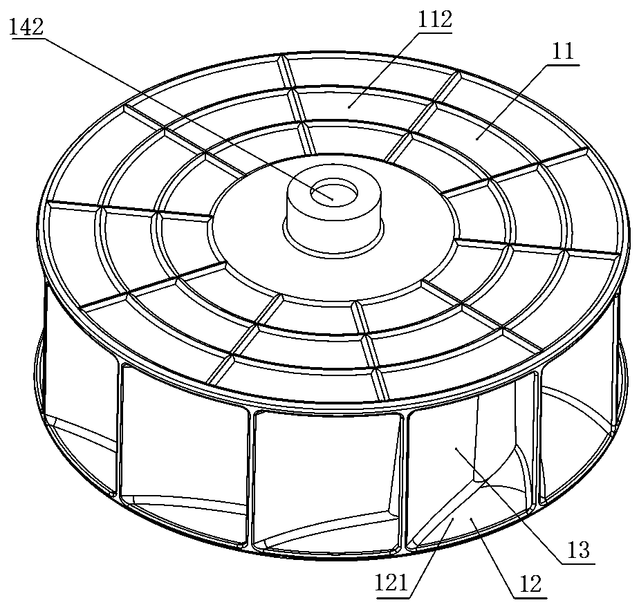
[0020] Figure 1 to Figure 4 The centrifugal impeller shown includes a front disc 12, a blade 13, and a rear disc 11. The front disc 12 and the rear disc 11 are two disc-shaped bodies located on the upper and lower sides of the blade 13, which constitute the installation base of the blade 13, and the blade 13 is located in the front Between the disc 12 and the rear disc 11, the front disc 12, the blades 13, and the rear disc 11 are integrally formed.

[0021] It should be noted that the so-called up, down, height, horizontal, vertical and other words related to orientation in the present invention are described based on the direction shown in the drawings as a standard, and do not mean the actual assembly or running direction. , and it should be understood as a general direction, and should not be limited to the absolute value in the geometric sense, because a little error in assembly absolutely exists and should be allowed.

[0022] It can be seen that the front disk 12 is h...


PUM


Abstract

The invention provides a centrifugal impeller injection molding mold with high adaptability. According to the technical scheme provided by the invention, the centrifugal impeller injection molding mold comprises a movable mold and a static mold, wherein the static mold comprises a central post and a mold core unit; the mold core unit comprises an upper core block and a lower core block; the upper core block and the lower core block are in linkage assembly; the lower core block has longitudinal height variation; the upper core block has a transverse movement path; the transverse movement path is of a linear configuration; the central post is limited to act on the lower core block; the upper core block comprises an upper core block matching surface; the lower core block comprises a lower core block matching surface; and the upper core block matching surface and the lower core block matching surface are respectively of a plane configuration and are respectively inclined relative to the transverse movement path.

Description

technical field [0001] The invention relates to a mold for manufacturing a centrifugal impeller through an integral molding process of injection molding. Background technique [0002] Centrifugal impeller refers to a wind wheel that takes air in axially and leaves air radially, and uses centrifugal force (depending on the speed and outer diameter) to do work to increase the pressure of the air. Traditional molds for manufacturing centrifugal impellers through the injection molding process can only advance and retreat horizontally. When manufacturing centrifugal impellers with vertical height changes, they will have to be independently injection-molded through multiple molds for specific parts, and then manually. Weld the parts obtained in the previous steps into a whole again. Time-consuming and labor-intensive, low production efficiency, not suitable for mass production, and the strength of the connection structure welded at multiple parts is low, which cannot meet the per...

Claims


Application Information

Patent Timeline
Patent Type & Authority Patents(China)
IPC IPC(8): B29C45/26B29C45/33B29L31/08
CPCB29C45/26B29C45/332B29L2031/08
Inventor 黄志晓
Owner 永嘉县通洋环保科技有限公司
Learn More