
Built-in brake pedal travel sensor device

A stroke sensor and sensor device technology, which is applied in the direction of braking action starting devices, brakes, foot starting devices, etc., can solve the problems of inconvenient installation and layout, complex structure of stroke sensors, etc., and achieve compact structure, good process inheritance and reliability. sex high effect

Pending Publication Date: 2017-12-12
AUTOMOBILE RES INST OF TSINGHUA UNIV IN SUZHOU XIANGCHENG +1
View PDF7 Cites 3 Cited by
  • Summary
  • Abstract
  • Description
  • Claims
  • Application Information

AI Technical Summary

Problems solved by technology

However, the stroke sensor has problems such as complex structure and inconvenient installation and arrangement.

Method used


Image

  • Built-in brake pedal travel sensor device
  • Built-in brake pedal travel sensor device

Examples


Embodiment Construction

[0020] The technical solutions of the present invention will be further described below in conjunction with the accompanying drawings and specific embodiments.

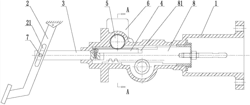
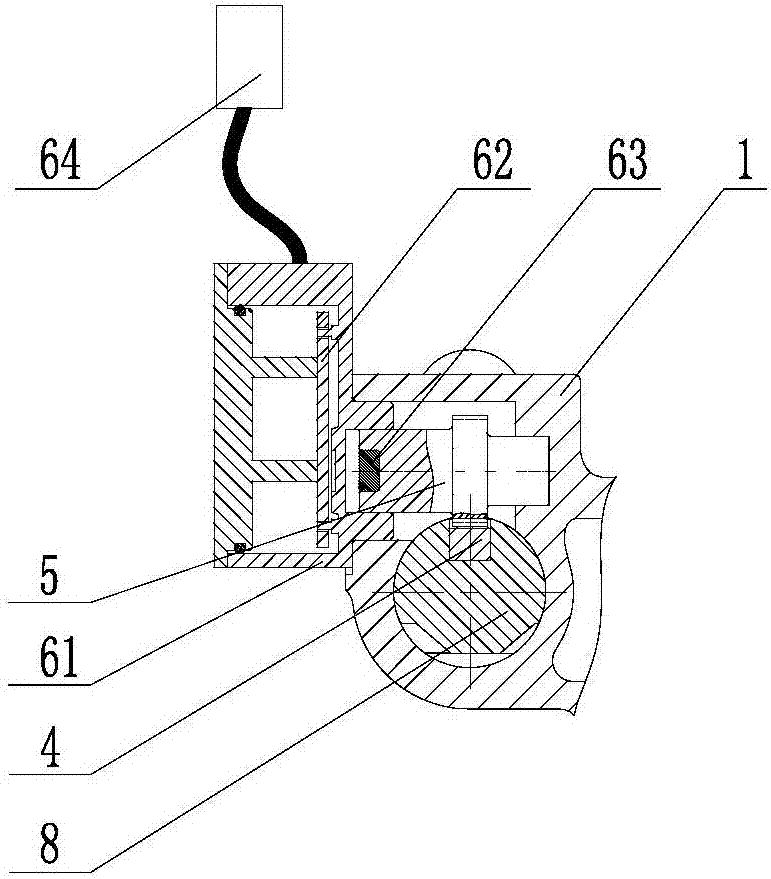
[0021] see figure 1 with figure 2 The shown built-in brake pedal stroke sensor device includes a housing 1 , a brake pedal 2 , a first push rod 3 , a rack 4 , a gear 5 and a stroke sensor assembly 6 for detecting the stroke of the brake pedal 2 .

[0022] The brake pedal 2 is the brake pedal of a conventional vehicle, one end of the brake pedal 2 is hinged on the pedal bracket positioned at the front of the car body, and one end of the first push rod 3 can be rotated and slidably connected to the brake pedal. 2, the first push rod 3 is slidably set relative to the housing 1.

[0023] Specifically, the brake pedal 2 is rotationally connected to one end of the first push rod 3 through a pin shaft 7, and the brake pedal 2 is provided with a first sliding groove 21 extending along its length direction, and the pin shaf...


PUM


Abstract

The invention discloses a built-in brake pedal travel sensor device. The built-in brake pedal travel sensor device comprises a shell, a brake pedal, a first push rod in rotating and sliding connection with the brake pedal, the brake pedal can rotate relative to the shell, and the first push rod can slide relative to the shell; the sensor device further comprises a rack arranged in the shell in a sliding manner, a gear meshed with the rack, a travel sensor assembly used for detecting the travel of the brake pedal, the rack is fixedly connected with the first push rod and is rotationally arranged on the shell, the travel sensor assembly comprises a sensor fixedly arranged on the shell, and the sensor is a Hall type sensor and is electrically connected with a vehicle-mounted controller; and the travel sensor assembly further comprises sensing magnetic steel fixedly arranged on the gear. The sensor device is compact in structured and high in reliability, the Hall principle is adopted for detection, and meanwhile, the beneficial effects of non-contact, high resolution ratio, vibration resistant, abrasion resistance, small power consumption, convenient installation and the like are achieved.

Description

technical field [0001] The invention specifically relates to the technical field of auto parts, in particular to a built-in brake pedal travel sensor device. Background technique [0002] Brake pedal sensors on early vehicles were primarily switch-type and could only detect when the brake pedal was disengaged or engaged. With the development of automotive application technology, it is necessary to provide a continuously changing full-travel signal during the braking process of the brake pedal. At present, the brake pedal stroke sensor on the market is mainly installed at the coaxial position of the hinge shaft of the brake pedal, so that the stroke sensor can be rotated by the rotation of the brake pedal during the braking process, so that the stroke sensor can output a signal. And the change of the output signal is used to detect the travel of the brake pedal. Although this method is simple in principle, its installation structure is relatively complicated, and the arra...

Claims


Application Information

Patent Timeline
Patent Type & Authority Applications(China)
IPC IPC(8): B60T7/04G01D5/14
CPCG01D5/145B60T7/042
Inventor 丁延超沈建州郑奎丁能根
Owner AUTOMOBILE RES INST OF TSINGHUA UNIV IN SUZHOU XIANGCHENG
Learn More