V-shaped support spiral lifting platform

A technology of spiral lift and spiral lift, which is applied in the field of V-shaped support type spiral lift platform, can solve the problems of smaller lifting weight, larger space size requirements, and high body height, and achieve the solution of space size, compact space structure, and structural well-designed effects

Inactive Publication Date: 2017-12-12
WUHU C&K AUTOMATION TECH CO LTD
View PDF6 Cites 0 Cited by
  • Summary
  • Abstract
  • Description
  • Claims
  • Application Information

AI Technical Summary

Problems solved by technology

Most of the existing stage equipment is the traditional hydraulic cylinder, pneumatic cylinder, or screw method, etc. During the lifting process, the traditional lifting method will gradually reduce the lifting weight according to the increase

Method used


Image

  • V-shaped support spiral lifting platform
  • V-shaped support spiral lifting platform
  • V-shaped support spiral lifting platform

Examples


Embodiment 1

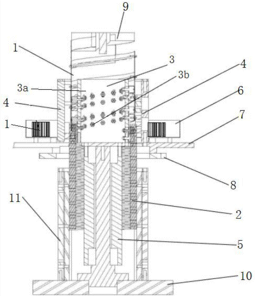
[0043] The screw jack 19 includes a fixed base, a platform that rotates around the fixed base, a storage box 6 installed on the platform, a spring flat belt 1 stored in the storage box 6, installed in the fixed base and flat with the spring The belt 1 cooperates with the toothed spring bar 2 forming the spiral cylinder, and the belt track lifting mechanism installed on the platform is used to bind the toothed spring bar 2 to lift or shrink. 3. It is used to make the spring flat belt 1 and the toothed spring bar 2 snapping track guides 4 . The motor 19 drives the platform to rotate, and then drives the belt track lifting mechanism 3 to rotate, and the belt track lifting mechanism 3 makes the toothed spring bar 2 rise and fall under the guidance of the belt track lifting mechanism 3, and synchronously pulls the spring flat belt 1 to spirally climb , Under the pushing action of the track guide frame 4, the spring flat belt 1 and the toothed spring bar 2 engage and form a spiral r...

Embodiment 2

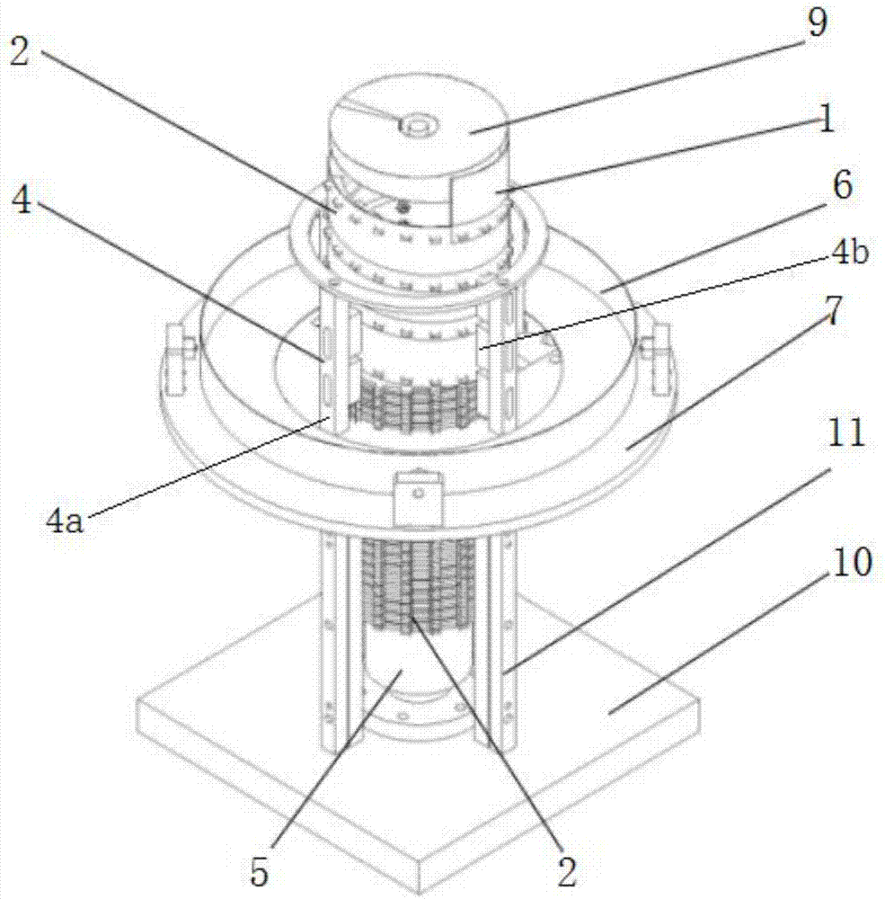
[0059] Such as Figure 9 to Figure 12 As shown, the screw jack 19 includes a fixed base, a platform that rotates around the fixed base, a storage box 6 installed on the platform, a spring flat belt 1 stored in the storage box 6, installed in the fixed base and Cooperate with the spring flat belt 1 to form the toothed spring bar 2 of the spiral cylinder, the belt track lifting mechanism installed on the platform for binding the toothed spring bar 2 to lift or shrink the movement 3, used to make the spring flat belt 1 and the tooth The track guide frame 4 that type spring bar 2 interlocks. The motor 19 drives the platform to rotate, and then drives the belt track lifting mechanism 3 to rotate, and the belt track lifting mechanism 3 makes the toothed spring bar 2 rise and fall under the guidance of the belt track lifting mechanism 3, and synchronously pulls the spring flat belt 1 to spirally climb , Under the pushing action of the track guide frame 4, the spring flat belt 1 and ...


PUM


Abstract

The invention relates to a V-shaped support spiral lifting platform. The V-shaped support spiral lifting platform comprises a spiral lifter fixed on the ground, a motor for driving the spiral lifter to lift, and an object carrying table mounted at the upper end of the spiral lifter; and a V-shaped support bracket is mounted between the object carrying table and the ground. The V-shaped support spiral lifting platform further comprises a controller for controlling operation of the motor. The V-shaped support spiral lifting platform is reasonable in structural design, combines the spiral lifter with the V-shaped support bracket to realize the lifting movement of the object carrying table, is compact in space structure, and solves the technical difficulty of larger space size occupied by a traditional lifting mechanism; and the lifting force cannot be suddenly reduced due to increment of the lifting height, so that the stability is higher, and the safety is high.

Description

technical field [0001] The invention relates to the technical field of lifting equipment, in particular to a V-shaped support type spiral lifting platform. Background technique [0002] Lifting equipment is more common in people's daily life, such as scissor lifting trolleys for street lamp repair, hydraulic cylinder lifting stages used in large playgrounds, evening parties, etc. Most of the existing stage equipment is the traditional hydraulic cylinder, pneumatic cylinder, or screw method, etc. During the lifting process, the traditional lifting method will gradually reduce the lifting weight according to the increase in height, and the height of the body will increase with the lifting height. Ascent and higher, more limited. Traditional lifting equipment has a large requirement for space size, resulting in bulky equipment, which cannot be used in small spaces. Therefore there is an urgent need for a new lifting device. Contents of the invention [0003] The technical ...

Claims


Application Information

Patent Timeline
IPC IPC(8): B66F7/14B66F7/28
CPCB66F7/14B66F7/28
Inventor 金虎杰
Owner WUHU C&K AUTOMATION TECH CO LTD
Why Eureka
Try Eureka