Powerful sports sealed suction device

A sporty and powerful technology that can be used in vacuum cleaners, household appliances, cleaning equipment, etc., to solve problems such as inability to clean up

Inactive Publication Date: 2019-08-20
张先池
View PDF7 Cites 0 Cited by
  • Summary
  • Abstract
  • Description
  • Claims
  • Application Information

AI Technical Summary

Problems solved by technology

[0004] The above-mentioned technical solution adopts the roller bristles to clean up the garbage, but the roller bristles cannot clean up the accumulated water on the ground, and the roller bristles cannot maintain a dynamic seal during movement.

Method used


Image

  • Powerful sports sealed suction device
  • Powerful sports sealed suction device
  • Powerful sports sealed suction device

Examples


Embodiment 1

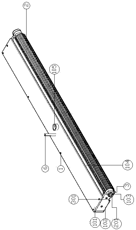
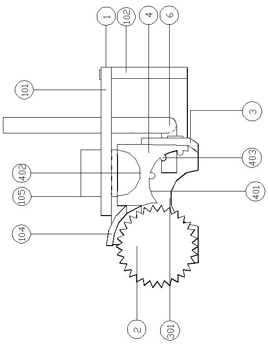
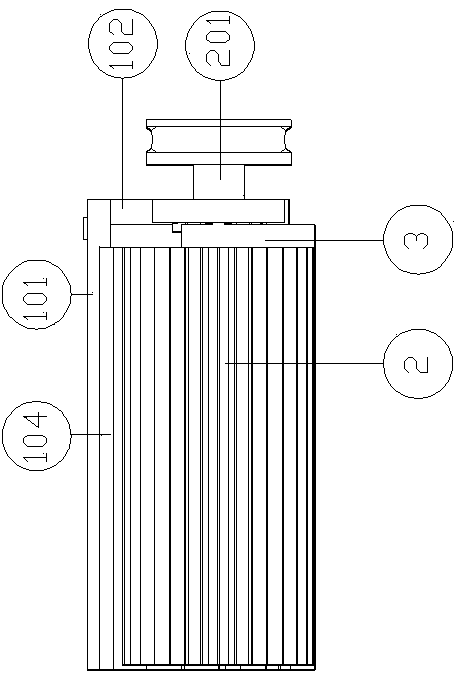
[0030] Embodiment one: if Figure 1-6 , a powerful motion sealed suction device, including a casing 1, a straight-toothed rubber roller 2, and a rubber scraper 3, wherein the casing 1 is composed of a horizontal plate 101 and a vertical plate 102, wherein the horizontal plate 101 and the vertical plate 102 Both are plastic plates or metal plates, and the bottom surface of the horizontal plate 101 is connected with a vertical plate 102 by bolts, wherein the vertical plate 102 is formed by bending two ends of a plastic plate or a metal plate, wherein the two ends of the vertical plate 102 are fixed There is a bearing seat, and a bearing 103 is fixed in each bearing seat, and a rotating shaft 201 is fixed in the inner ring of each bearing 103 through a flat key, and a straight-toothed rubber roller 2 is inserted on the rotating shaft 201, and the straight-toothed rubber roller The cylinder 2 is a cylindrical roller with straight tooth grooves on the surface. The teeth of the stra...

Embodiment 2

[0031] Embodiment two: except that following structure is different, all the other are all with embodiment one:

[0032] Such as Figure 7 , the teeth of the straight-toothed rubber roller 2 are consistent with those of the shifting gear, which increases the service life of the straight teeth of the straight-toothed rubber roller 2 and prevents the glass from easily displacing the straight teeth of the straight-toothed rubber roller 2 Cuts result in reduced sealing performance.

Embodiment 3

[0033]Embodiment three: except that following structure is different, all the other are all with embodiment one:

[0034] Such as Figure 8 , where the rear end face of the vertical plate 102 and the bottom of the bearing seats at both ends of the vertical plate 102 are welded with threaded sleeves 501, and each threaded sleeve 501 is screwed into a matching bolt, and the bottom of the bolts is welded with floor rollers 5. The landing roller 5 is a universal wheel, and the direction can be adjusted freely. By rotating the bolt to adjust the length of the bolt extending out of the threaded sleeve 501, the relative position of the straight-toothed rubber roller 2 to the ground can be adjusted, so that the straight-toothed rubber roller The straight teeth of the roller 2 will not generate greater frictional force with the ground, resulting in the non-rotation of the straight toothed rubber roller 2, thus losing the functions of sealing and cleaning dirt.


PUM


Abstract

The invention discloses a powerful motion type sealed object absorption device. The device comprises a shell, a straight tooth-shaped rubber roller and a rubber scraper, the shell is formed by a horizontal plate and vertical plates in an enclosing mode, bearing pedestals are fixed to the two ends of the vertical plates, bearings are fixed in the bearing pedestals, a rotating shaft is fixed in the bearings, and the rotating shaft is sleeved with the straight tooth-shaped rubber roller; baffles are fixed to the vertical plates; a plastic piece is fixed to each vertical plate. Accordingly, the straight tooth-shaped rubber roller is adopted, water and objects can be swept into an airflow passage, and meanwhile motive seal can be achieved; raised lines are fixed to the plastic blocks, and wet scrap paper cannot be attached to the plastic blocks completely and can be absorbed away under negative pressure; a water pump and a motor are fixed to the horizontal plate, and the phenomenon that the straight tooth-shaped rubber roller rotates automatically, and meanwhile the ground is cleaned with water can be achieved; due to the fact that the straight tooth-shaped rubber roller and the rubber scraper form a seal, suction in the airflow passage is very large, and garbage and accumulated water on the ground can be cleaned away.

Description

technical field [0001] The invention relates to the field of household garbage cleaning, in particular to a powerful motion type sealed suction device for cleaning smooth floors. Background technique [0002] Most of the current floor cleaning uses vacuum cleaners, sweeping robots and floor cleaning machines, and a small part continues to use manual cleaning such as brooms and mops. Nowadays, all cleaning equipment at home and abroad have single functions and cannot clean the ground dust, cigarette butts, and paper scraps. and liquid stains on the ground, etc. to clean and absorb at the same time. [0003] CN 2801724Y discloses a cleaning device for conveyors, which includes a roller brush cylinder, the roller brush cylinder is composed of roller bristles, and the roller brush cylinder pulley is fixed by a bearing seat. [0004] The above-mentioned technical solution adopts the rolling bristles to clean up the garbage, but the rolling bristles cannot clean up the accumulate...

Claims


Application Information

Patent Timeline
Patent Type & Authority Patents(China)
IPC IPC(8): A47L7/00
Inventor 张先池
Owner 张先池
Why Eureka
Try Eureka