Ornamental device with protection function

A technology for protection and equipment, applied in the field of viewing equipment with protection function, can solve problems such as hidden safety hazards, difficulty in realizing automatic access and rotation, etc.

Pending Publication Date: 2021-07-09
朱孔招
View PDF7 Cites 5 Cited by
  • Summary
  • Abstract
  • Description
  • Claims
  • Application Information

AI Technical Summary

Problems solved by technology

[0004] In order to overcome the shortcomings of the existing storage equipment, there are potential safety hazards, and it is difficult to achieve the effect of automatic access and rotation, the technical problem is: to provide a protective ornamental device that can realize automatic access and rotation and high safety

Method used


Image

  • Ornamental device with protection function
  • Ornamental device with protection function
  • Ornamental device with protection function

Examples


Embodiment 1

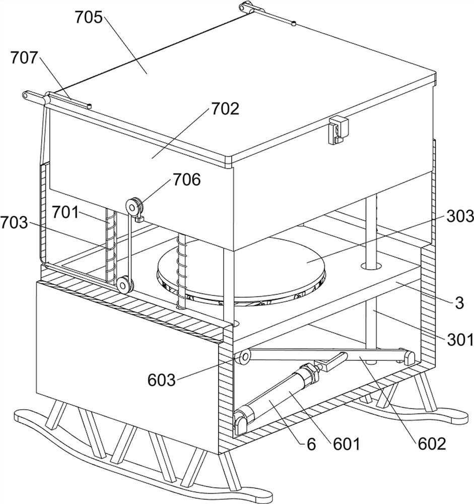
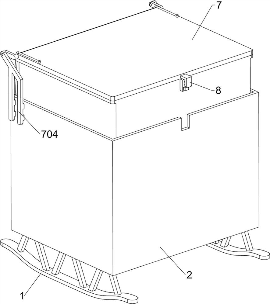
[0054] A protective ornamental device such as figure 1 , figure 2 and Figure 4 As shown, it includes a first bracket 1, a frame body 2, a placement assembly 3, a servo motor 4 and a rotation assembly 5, a frame body 2 is provided between the top of the first bracket 1, and a placement assembly 3 is provided on the frame body 2, and the placement assembly 3 is placed on the frame body 2. The component 3 is provided with a servo motor 4 , and a rotating component 5 is provided between the output shaft of the servo motor 4 and the placement component 3 .

[0055] Placement assembly 3 includes guide rod 301, support plate 302, placement plate 303 and pulley 304, frame body 2 is provided with guide rod 301 on four sides, and support plate 302 is slidably connected between guide rod 301, and support plate 302 middle The placement plate 303 is rotationally connected, the bottom of the placement plate 303 is evenly rotationally connected with a pulley 304, and the pulley 304 is co...

Embodiment 2

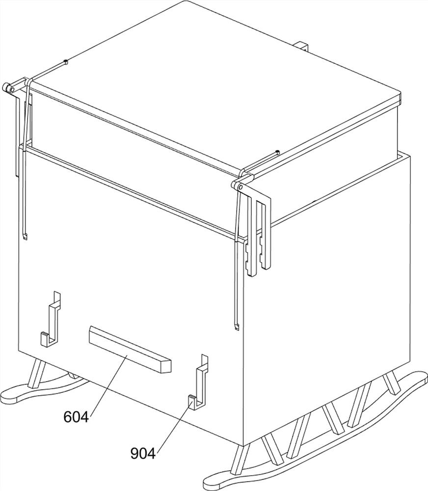
[0059] On the basis of Example 1, such as Figure 1-5 As shown, a lifting assembly 6 is also included. The lifting assembly 6 includes a cylinder 601, a rotating rod 602, a contact wheel 603, and a touch switch 604. The left front and right rear sides of the inner bottom wall of the frame body 2 are rotatably connected to the cylinder 601. , the right front side and the left rear side of the inner bottom wall of the frame body 2 are rotatably connected with a rotating rod 602, and a contact wheel 603 is rotatably installed on the rotating rod 602, and the contact wheel 603 is in contact with the support plate 302. Touch switch 604 .

[0060] After placing the ornament, you need to adjust the height of the ornament, you can press the touch switch 604 to make the cylinder 601 stretch, drive the rotating rod 602 to rotate, make the contact wheel 603 rotate and move the support plate 302 upward, and then make the ornament To move upwards, when it is necessary to lower the ornamen...


PUM


Abstract

The invention relates to an ornamental device, in particular to an ornamental device with a protection function. The technical problem is to provide the ornamental equipment with the protection function, which can realize automatic access and rotation and is high in safety. According to the technical scheme, the ornamental equipment with the protection function comprises first supports and a frame body, and the frame body is arranged between the tops of the first supports; a placing assembly which is arranged on the frame body; a servo motor which is arranged on the placing assembly; and a rotating assembly which is arranged between the output shaft of the servo motor and the placing assembly. And through cooperation of the placing assembly, the servo motor and the rotating assembly, the ornamental article can be automatically rotated, and tourists can conveniently watch the ornamental article.

Description

technical field [0001] The invention relates to an ornamental device, in particular to an ornamental device with protection function. Background technique [0002] With the continuous development of the social economy, more and more industries continue to rise. Many archaeologists have never given up on the research of archaeological objects. Many of the antiquities left over from ancient times have been distributed by the state to various museums across the country. Nowadays, there are also many professionals who study artworks to pursue precious artworks. Museums and art galleries will store some precious items for tourists to watch. [0003] The equipment for storing these ancient objects and works of art will have potential safety hazards, and it is difficult to realize the effect of automatic access and rotation. Therefore, a protective viewing device with automatic access and rotation and high security is now developed. Contents of the invention [0004] In order to...

Claims


Application Information

Patent Timeline
Patent Type & Authority Applications(China)
IPC IPC(8): A47F3/11A47F3/06A47F3/00A47F7/00
CPCA47F3/00A47F3/004A47F3/06A47F3/11A47F7/00
Inventor 朱孔招
Owner 朱孔招
Why Eureka
Try Eureka