
Tension mechanism of paying-off device

A technology of tensioning mechanism and pay-off device, which is applied in the field of tensioning mechanism, can solve problems such as subsidence, line jamming, and inability to meet high-efficiency production requirements, and achieve the effect of ensuring the stability of cooperation

Inactive Publication Date: 2017-12-15
HEFEI SMARTER TECH GROUP CORP
View PDF7 Cites 0 Cited by
  • Summary
  • Abstract
  • Description
  • Claims
  • Application Information

AI Technical Summary

Problems solved by technology

During the pay-off process, the aluminum rod or aluminum alloy rod is pulled out by pulling force, and this kind of pay-off method is from the outside to the inside, which is prone to unstable phenomena such as wire jamming and collapse during the pay-off process. The existing rack-mounted pay-off racks can no longer meet the requirements of efficient production

Method used


Image

  • Tension mechanism of paying-off device
  • Tension mechanism of paying-off device
  • Tension mechanism of paying-off device

Examples


Embodiment Construction

[0021] The purpose of this specific embodiment is to provide a tensioning mechanism of a pay-off device, which can ensure the stability of the coil and prevent the coil from being stuck or collapsed during the pay-off process.

[0022] Hereinafter, an embodiment will be described with reference to the drawings. In addition, the examples shown below do not limit the content of the invention described in the claims in any way. In addition, all the contents of the configurations shown in the following embodiments are not limited to be essential to the solution of the invention described in the claims.

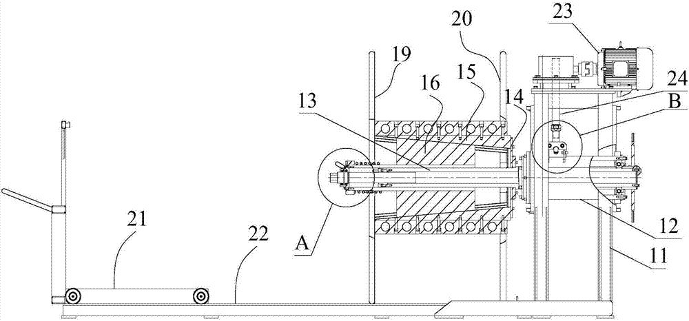
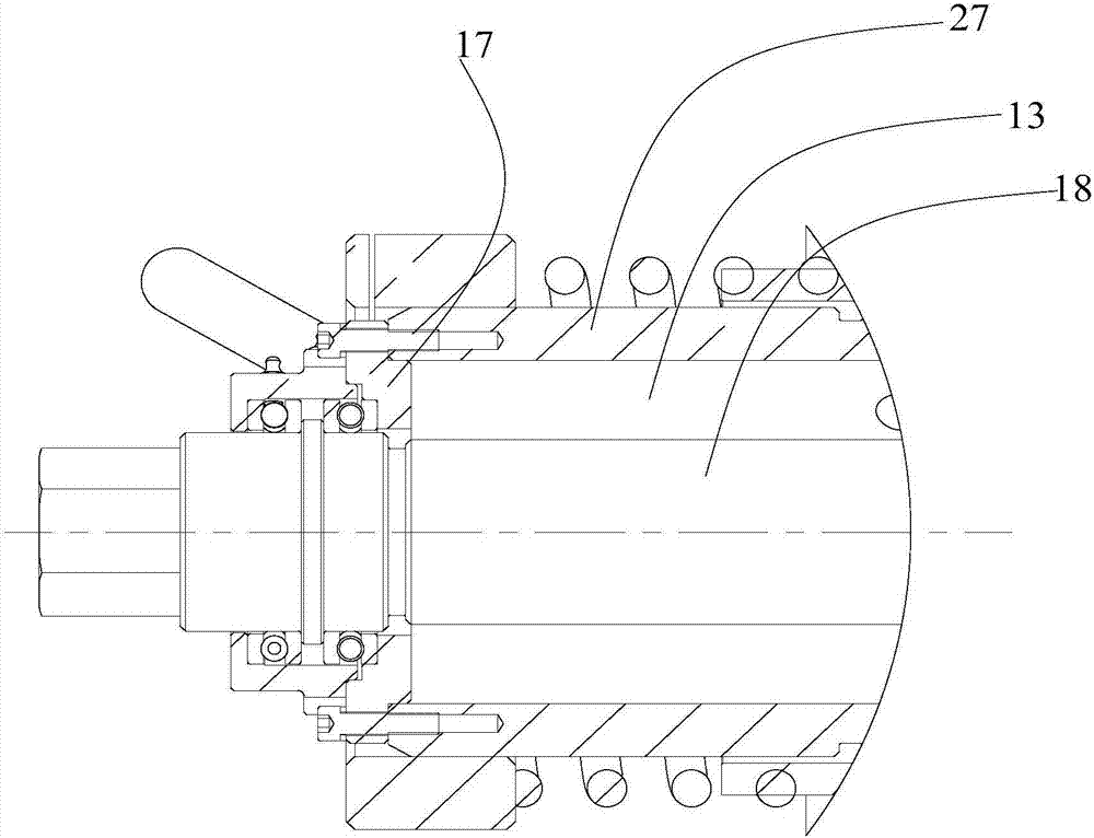
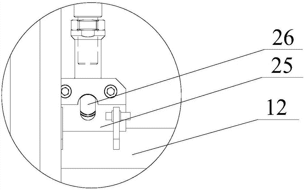
[0023] see Figure 1-Figure 3 , the tensioning mechanism of the pay-off device provided in this embodiment, the guide disc 14, a plurality of radially moving blocks 15, the axially moveable block 16 and the axial drive mechanism, wherein the guide disc 14 is fixedly arranged on the main shaft of the pay-off device 13, a plurality of radially moving blocks 15 are distributed alon...


PUM


Abstract

The invention discloses a tension mechanism of a paying-off device. The tension mechanism comprises a guiding disc, a plurality of radial moving blocks, axial moving blocks and an axial driving mechanism, wherein the guiding disc is fixedly arranged on a main shaft of the paying-off device; the radial moving blocks are distributed in the circumferential direction of the main shaft, and a radial guiding groove and a protrusion structure matched with the corresponding radial guiding groove are arranged between each radial moving block and the guiding disc; the axial moving blocks are surrounded in the radial moving blocks, the axial moving blocks can move in the axial direction of the main shaft, the matched surfaces of the radial moving blocks and the axial moving blocks are bevels, and the axial moving blocks drive the radial moving blocks to expand outwards when the axial moving blocks are displaced forward in the axial direction; the axial moving blocks drive the radial moving blocks to retract inwards when the axial moving blocks are displaced reversely in the axial direction; and the axial driving mechanism is used for driving the axial moving blocks to move axially. In this way, according to the tension mechanism of the paying-off device, the stability of a coil can be ensured, and the problems of wire clamping and collapsing of the coil in the paying-off process can be prevented.

Description

technical field [0001] The invention relates to the technical field of cable take-up and pay-off, and more specifically, to a tensioning mechanism of a pay-off device. Background technique [0002] The domestic rolling mill adopts a loose coil-type closing rod, and a frame-mounted pay-off frame is used in the subsequent process to pay off the wire. In the prior art, aluminum rods or aluminum alloy rods are coiled into coils, and the rack-mounted pay-off method is adopted when paying off. During the pay-off process, the coils are fixed and the axial direction is vertical. During the pay-off process, the aluminum rod or aluminum alloy rod is pulled out by pulling force, and this kind of pay-off method is from the outside to the inside, which is prone to unstable phenomena such as line jamming and collapse during the pay-off process. The existing rack-mounted pay-off Racks can no longer meet the requirements of efficient production. Contents of the invention [0003] In vie...

Claims


Application Information

Patent Timeline
Patent Type & Authority Applications(China)
IPC IPC(8): B21C47/18B21C47/24B21C47/28
CPCB21C47/18B21C47/24B21C47/28
Inventor 管东风盛卫国卢慧李佳鹏
Owner HEFEI SMARTER TECH GROUP CORP
Learn More