Chain plate pin shaft and machining process thereof

A processing technology and chain plate technology, applied in the direction of pins, chain rings, transmission chains, etc., can solve the problem of poor cooperation between the end 2 and the groove 40, the reduction of the force bearing area of ​​the mating surface, and the difficulty in achieving a smooth transition, etc. problem, to achieve the effect of improving service life and use effect, reducing stress concentration and reducing scratches

Active Publication Date: 2020-08-25
上海兴道锻造有限公司
View PDF8 Cites 0 Cited by
  • Summary
  • Abstract
  • Description
  • Claims
  • Application Information

AI Technical Summary

Problems solved by technology

[0005] And in order to avoid stress concentration at the matching position between the end head 2 and the groove 40, the right angle of the end head 2 is generally set as a rounded corner 32, thereby avoiding the gap between the right angle of the end head 2 and the inner right angle of the groove 40. direct contact, thereby reducing stress concentration, but the junction between the fillet 32 ​​of the end 2 and the plane of the end 2 is difficult to achieve a smooth transition in actual processing, that is, the junction is relatively sharp, so when the chain vibrates and the end When there is a relatively small displacement between the head 2 and the groove 40, the sharp point is easy to scratch the mating surface of the groove 40, resulting in poor matching conditions between the end head 2 and the groove 40, and the mating surface is damaged. The force area is reduced, resulting in stress concentration, which in turn reduces the service life of the chain

Method used


Image

  • Chain plate pin shaft and machining process thereof
  • Chain plate pin shaft and machining process thereof
  • Chain plate pin shaft and machining process thereof

Examples


Embodiment 1

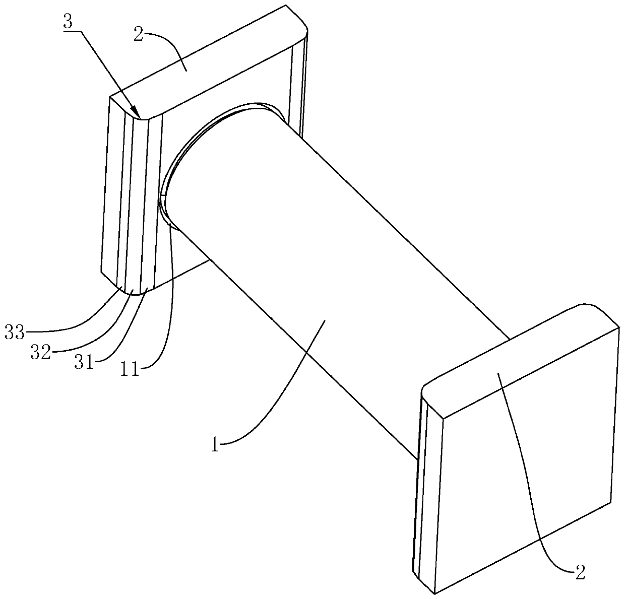
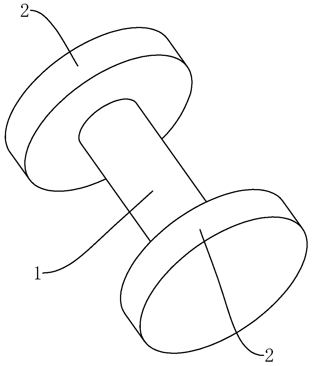
[0057] Embodiment 1: as figure 1 As shown, it is a chain plate pin disclosed by the present invention, which includes a shaft body 1 and two square ends 2 symmetrically fixed to one side of the shaft body 1 .

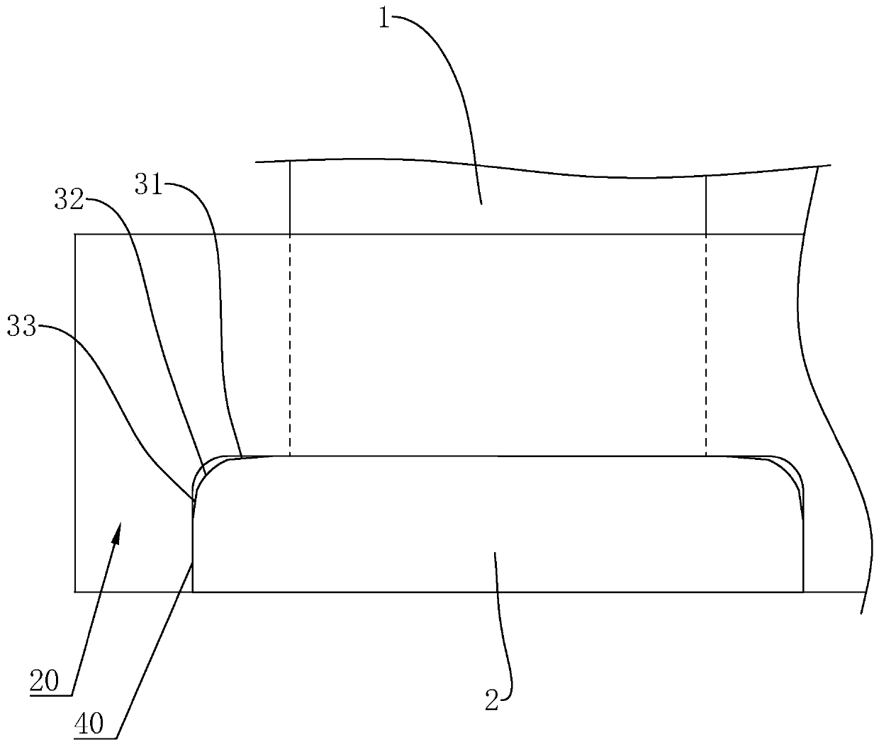
[0058] The surface roughness of the peripheral surface of the shaft body 1 is less than 0.25 μm, and an undercut 11 is provided at the junction between the peripheral surface of the shaft body 1 and the inner end surface of the end head 2; by defining the surface of the peripheral surface of the shaft body 1 The roughness improves the surface quality of the peripheral surface of the shaft body 1, thereby improving the cooperation between the peripheral surface of the end head 2 and the inner chain plate 30, and further improving the service life and use effect of the chain.

[0059] The diameter of the shaft body 1 is D. When 10mm

Embodiment 2

[0064] Embodiment 2: A kind of processing technology of chain plate pin shaft, comprises the following steps:


PUM

PropertyMeasurementUnit
surface roughnessaaaaaaaaaa

Abstract

The invention relates to a chain plate pin shaft and a machining process thereof. The chain plate pin shaft comprises a shaft body and two square ends symmetrically fixed to one side of the shaft body, a transition face is mounted on the junction of the long side face of one end and the inner end face of the other end, and the machining process of the chain plate pin shaft comprises the steps of S1, raw material inspection; S2, discharging; S3, medium frequency heating; S4, blank making; S5, forging forming; S6, side cutting; S7, annealing treatment; S8, chain plate pin shaft semi-finished product turning; S9, chain plate pin shaft semi-finished product heat treatment tempering; S10, chain plate pin shaft semi-finished product grinding; and S11, finished product warehousing. The transitionface is mounted to reduce the stress concentration between the ends and an outer chain plate groove, through finish machining of the inner end faces of the ends and the periphery of the shaft body, the surface precision and the structural strength can be improved, the cooperation condition of the ends and an outer chain plate and the cooperation condition of the shaft body and an inner chain plate are optimized, the service life of a chain can be prolonged, and the use effect of the chain can be improved.

Description

technical field [0001] The invention relates to the technical field of chain components, in particular to a chain plate pin shaft. Background technique [0002] In recent years, chain transmission has been widely used in the field of mechanical transmission because chain transmission can efficiently transmit power, high-speed chain transmission technology has been continuously matured, and maintenance costs can be reduced at the same time. [0003] At present, in the large-load chain structure, the head of the pin shaft is circular. When installing and using, it is necessary to insert the round head of the pin shaft into the circular through hole of the chain plate and fix it. Because the large-load chain is working During the process, the pin shaft will rotate in the circular through hole, and the rotation of the pin shaft will cause the chain plate to shear the pin shaft and cause the pin shaft to be damaged, which affects the service life of the chain. [0004] Therefore...

Claims


Application Information

Patent Timeline
Patent Type & Authority Applications(China)
IPC IPC(8): F16G13/06F16G15/12B23P15/14B23P15/00B21G3/28
CPCB21G3/28B23P15/00B23P15/14F16G13/06F16G15/12
Inventor 叶利剑
Owner 上海兴道锻造有限公司
Why Eureka
Try Eureka